Adhesive film, connecting method, and joined structure

a technology of adhesive film and connecting method, applied in the field of adhesive film, can solve problems such as short circuits, and achieve the effect of high conduction reliability

Active Publication Date: 2010-04-22
DEXERIALS CORP
View PDF15 Cites 23 Cited by
  • Summary
  • Abstract
  • Description
  • Claims
  • Application Information

AI Technical Summary

Benefits of technology

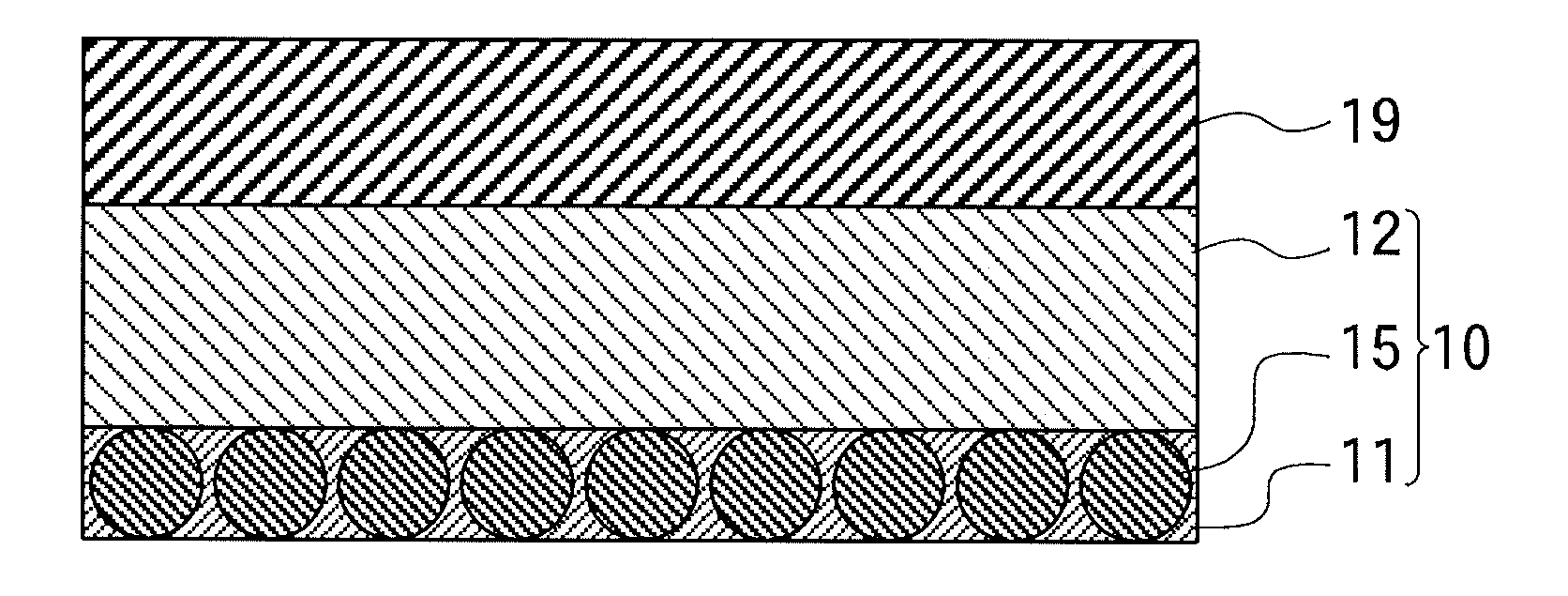
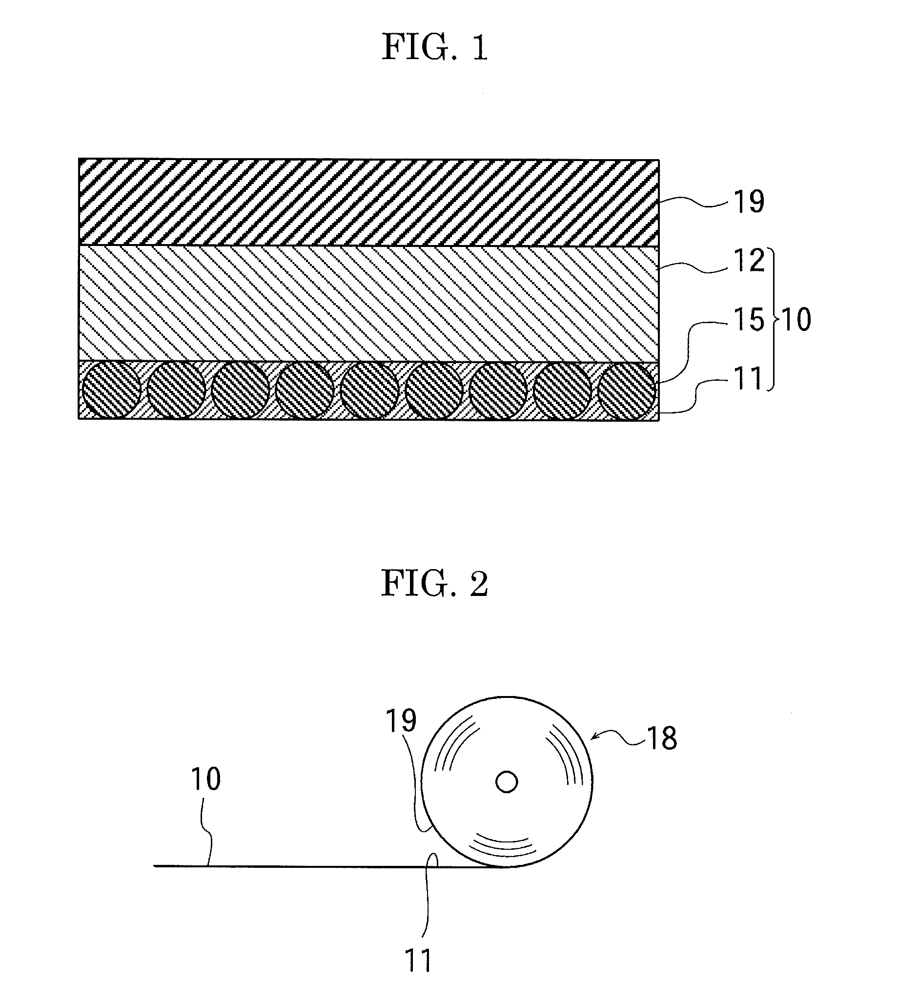
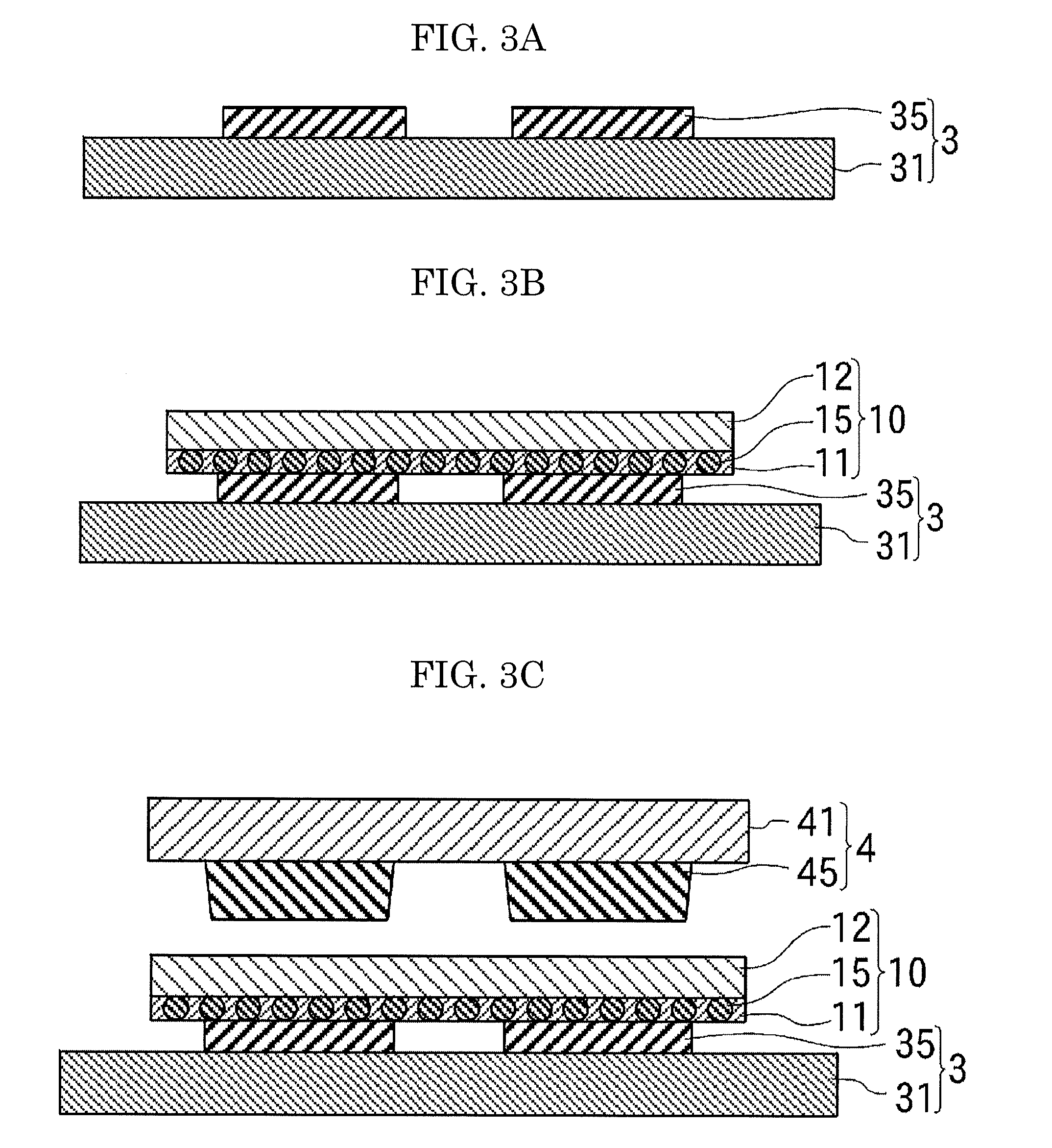
[0029]In the present invention, as the amount of the conductive particles pushed out from the space between the terminals facing to each other is decreased, the number of the conductive particles captured between the terminals facing to each other is increased, and thus a joined structure of high conduction reliability is attained without a short circuit due to the conductive particles present between the terminals adjacent to each other.

Problems solved by technology

However, when the binder is pushed out, part of the conductive particles are pushed out together with the binder, and the pushed conductive particles are moved into the space between the adjacent terminals of the substrate or the adjacent terminals of the electronic part, which may cause a short circuit due to the conductive particles present between the adjacent terminals.

Method used


Image

  • Adhesive film, connecting method, and joined structure
  • Adhesive film, connecting method, and joined structure
  • Adhesive film, connecting method, and joined structure

Examples


example

[0079]Hereinafter, the present invention is specifically explained with reference to examples and comparative examples thereof, but the examples shall not be construed as to limit the scope of the present invention.

[0080]Phenoxy resin, which was a solid resin, was made dissolved in a solvent (toluene / ethylacetate=1 / 1) to thereby obtain a solution having a solid content of 30% by weight.

[0081]Thereafter, a curing agent, epoxy resin, inorganic filler, a silane coupling agent, and conductive particles were added to and mixed in the solution so that the formulation thereof became as stated in the column “ACF” of Table 1, and then adjusted with toluene so as to have a solid content of 40% by weight to thereby obtain a solution of a joining material.

TABLE 1Formulation of AdhesiveProductSofteningnamepointACFNCF-1NCF-2Curing agentHX3941HP—50parts50parts53partsEpoxy resinEP828—9parts9parts13partsPhenoxyYP70 84° C.0part0part33partsresinFX280158° C.30parts30parts0partInorganic—10parts10parts0p...


PUM

PropertyMeasurementUnit
temperatureaaaaaaaaaa

Abstract

An adhesive film, containing a first adhesive layer in which conductive particles are dispersed, and a second adhesive layer adhered to the first adhesive layer, wherein the lowest viscosity of the first adhesive layer attained at or below the curing temperature is higher than that of the second adhesive layer attained at or below the curing temperature, where the curing temperature is a temperature at which the adhesive layer starts to cure, wherein the first and second adhesive layers are respectively disposed to a substrate side and an electronic part side, and the adhesive film is configured to join the electronic part and the substrate by heating and pressurizing the substrate and the electronic part with the adhesive layer being therebetween, and wherein the first adhesive layer has a thickness which is less than two times of an average particle diameter of the conductive particles.

Description

CROSS-REFERENCE TO RELATED APPLICATION[0001]This is a continuation of Application No. PCT / JP2008 / 061320, filed on Jun. 20, 2008.BACKGROUND OF THE INVENTION[0002]1. Field of the Invention[0003]The present invention relates to an adhesive film capable of connecting an electrical part to a substrate, a connection method thereof, and a joined structure.[0004]2. Description of the Related Art[0005]An anisotropic conductive adhesive, in which conductive particles are dispersed in an adhesive, has been conventionally used for a connection of an electronic part or a wiring board. When the anisotropic conductive adhesive is placed between the surface of the substrate where the terminals are disposed and the surface of the electronic part where the terminals are disposed, and heated and pressurized, the softened binder is pushed out from the space between the terminal of the substrate and the terminal of the electronic part, and the conductive particles are held between the terminal of the su...

Claims


Application Information

Patent Timeline
Patent Type & Authority Applications(United States)
IPC IPC(8): H05K1/16B32B7/12C09J7/00B32B37/12C09J7/10
CPCC09J7/00Y10T428/28C09J2201/36C09J2203/326H01L24/31H01L24/83H01L2224/16225H01L2224/83101H01L2224/83192H01L2224/838H01L2924/01005H01L2924/01013H01L2924/01015H01L2924/01027H01L2924/01033H01L2924/01058H01L2924/01074H01L2924/01078H01L2924/01079H01L2924/0781H01L2924/14H01R4/04H05K3/323H05K2201/10674H05K2203/1189H01L2224/2919H01L2924/01006H01L2924/01019H01L2924/01023H01L2924/0105H01L2924/0665C09J9/02H01L2224/83851H01L2224/293H01L2224/2929H01L2224/29082H01L2924/07811H01L24/29H01L2924/00C09J7/10C09J2301/208C09J7/35C09J7/22H01B5/16C09J2301/314C09J2203/00C09J2301/304C09J2301/408
Inventor ISHIMATSU, TOMOYUKIOZEKI, HIROKI
Owner DEXERIALS CORP
Why Eureka
Try Eureka