Motion Simulator, Display System, and Light-emissive Structures Typically Using Light-Emitting Diodes

a technology of light-emitting diodes and simulators, which is applied in the field of motion simulators, can solve the problems of reducing contrast, severe poor image uniformity across the full field of view, so as to reduce image distortion and astigmatism, reduce contrast, and reduce image quality and intensity. the effect of the virtual image seen by the observer

Inactive Publication Date: 2010-04-22
VIDEO DISPLAY CORP
View PDF8 Cites 14 Cited by
  • Summary
  • Abstract
  • Description
  • Claims
  • Application Information

AI Technical Summary

Benefits of technology

[0026]Additionally, configuring the present display system so that an observer in the simulator station receives light provided from the light-emissive components of the image-generating screen largely along their maximum light-intensity directions greatly reduces image distortion and astigmatism. The quality and intensity of the virtual image seen by the observer are both very high.
[0027]The present display system does not need any video projector(s) and thereby avoids the various difficulties, such as reduced contrast and poor image uniformity across the full field of view, arising from use of multiple projectors. By implementing the light-source modules with LEDs, the invention can take advantage of advances in LED technology, especially advances in LED surface-mount technology and organic LED technology. The invention thus provides a large advance over the prior art.

Problems solved by technology

Additionally, the tilting of collimating mirror 26 to screen 24 commonly produces severe image distortion and astigmatism.
This significantly reduces the contrast and can cause poor image uniformity across the full field of view.
In short, the image intensity and image quality of the conventional flight-simulation display system of FIGS. 1 and 2 are often undesirably low.
Furthermore, the geometric complexity of projector-based flight-simulation display systems such as that of FIGS. 1 and 2 commonly causes setup, maintenance and monitoring costs to be very high.
Performing image blending between adjacent channels across the projector overlap regions for reducing mismatch of brightness, contrast and color is invariably laborious and time consuming.
The cost of replacing light sources in projector-based flight-simulation display systems is considerable due to short lifetimes of light sources currently used in these projector-based systems.

Method used


Image

  • Motion Simulator, Display System, and Light-emissive Structures Typically Using Light-Emitting Diodes
  • Motion Simulator, Display System, and Light-emissive Structures Typically Using Light-Emitting Diodes
  • Motion Simulator, Display System, and Light-emissive Structures Typically Using Light-Emitting Diodes

Examples


Embodiment Construction

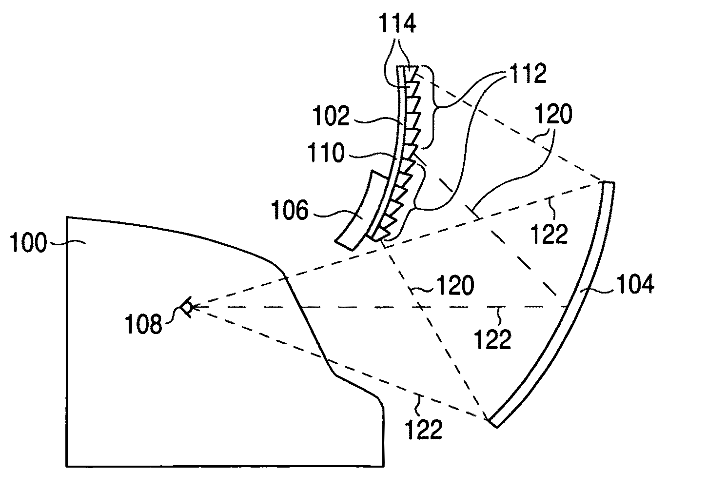
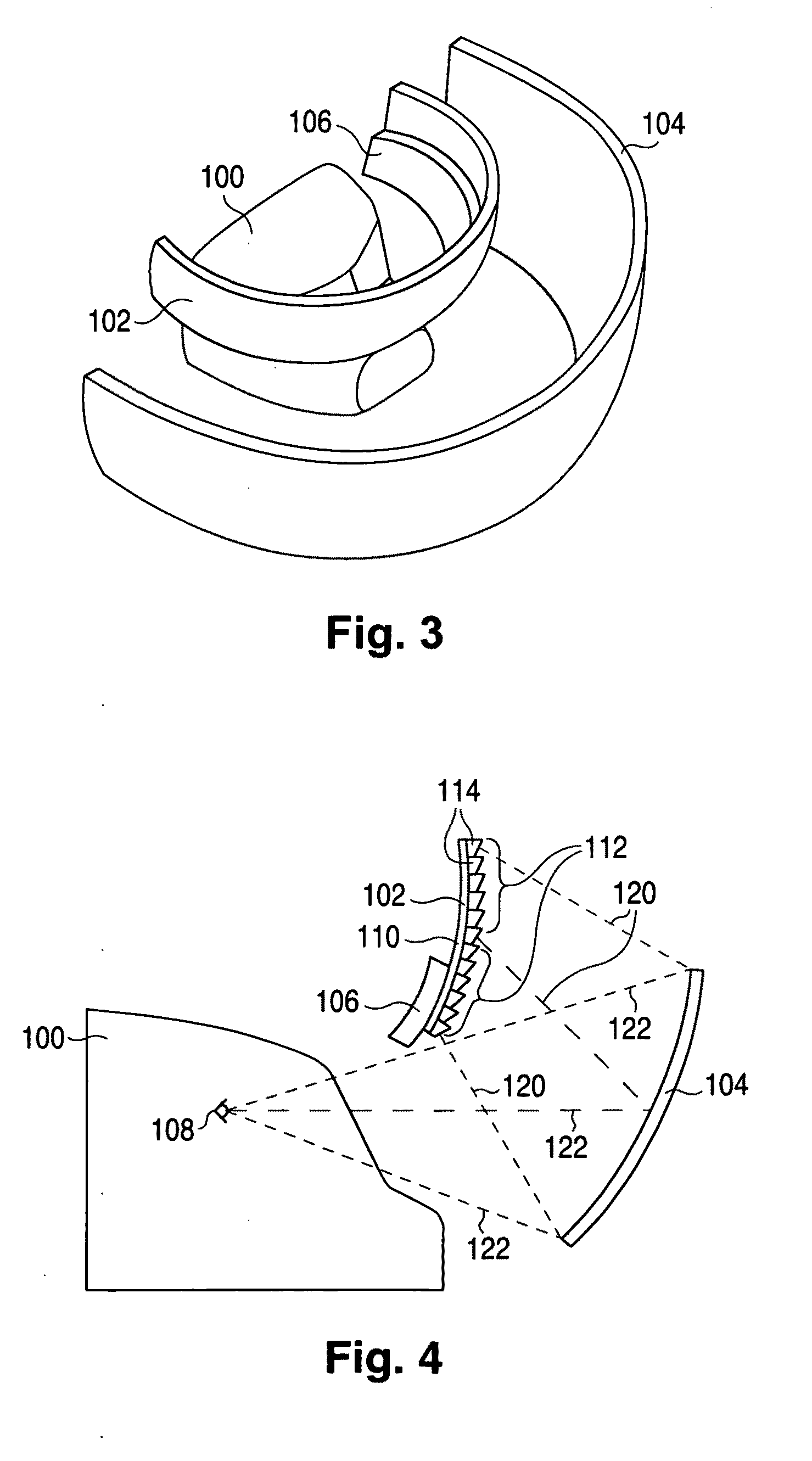
[0039]FIG. 3 illustrates a cross-cockpit flight simulator configured in accordance with invention. This flight simulator consists of a simulator cockpit 100 and a cross-cockpit flight-simulation display system formed with an active image-generating screen 102 of approximately spherical curvature, a collimating mirror 104 of spherical curvature, and screen supporting structure 106. Active image-generating screen 102 is generally shaped like a thin shell. The approximately spherically curved front (outside) surface of image-generating screen 102 has regular variations described below but, for simplicity, not illustrated in FIG. 3. Screen supporting structure 106, shown very generally in FIG. 3, physically supports image-generating screen 102 and contains some of the image-generating electronic circuitry.

[0040]Active image-generating screen 102, sometimes referred to as an image-generating thin-shell structure, actively generates a video image of a simulation of the external environmen...


PUM


Abstract

A light-emissive module (114), typically utilizing one or more LEDs (132R, 132G, and 132B), is configured so that the maximum intensity of the module's light emission occurs along a direction (138) materially non-perpendicular to the back surface (136) of the module's supporting body (130). An active image-generating screen (102) contains a plurality of block facets (112), each containing a plurality of the light-emissive modules arranged so that their maximum light-intensity directions are largely the same. The block facets are configured to approximate a curved surface. The maximum light-intensity directions (158) of the block facets are thus materially slanted to one another. The image-generating screen presents a video image. A display system suitable for a motion simulator, such as a flight simulator, is formed by combining the screen with a reflective collimator (104).

Description

CROSS-REFERENCE TO RELATED APPLICATION[0001]This claims priority to U.S. provisional patent application 61 / 196,263, filed 16 Oct. 2008, the contents of which are incorporated by reference to the extent not repeated herein.FIELD OF USE[0002]This relates to motion simulators, such as flight simulators, and to display systems suitable for motion simulators.BACKGROUND ART[0003]Flight simulators conventionally employ wide-angle panoramic collimated projection displays that provide high-fidelity seamless imagery for cross-cockpit / cab viewing. FIG. 1 illustrates such a conventional cross-cockpit flight simulator consisting of simulator cockpit 20 and a cross-cockpit flight-simulation display system formed with a group of video projectors 22, spherically curved back-projection screen 24, and spherically curved collimating mirror 26. Projectors 22 project video images onto the back of screen 24. The video images pass through back-projection screen 24 and appear on its front surface. Collimat...

Claims


Application Information

Patent Timeline
Patent Type & Authority Applications(United States)
IPC IPC(8): G09G3/32F21V21/00F21V9/00G09G3/34
CPCG02B17/0605G02B27/024G09B9/308G09G2380/12G09G3/02G09G3/3413G09G3/001F21V21/00G09B9/30G09B9/32G09B9/323G09B9/326
Inventor VIDAL, MARCIALLI, HAIZHANG
Owner VIDEO DISPLAY CORP
Why Eureka
Try Eureka