Liquid ejecting head and liquid ejecting apparatus
- Summary
- Abstract
- Description
- Claims
- Application Information
AI Technical Summary
Benefits of technology
Problems solved by technology
Method used
Image

Examples
first embodiment
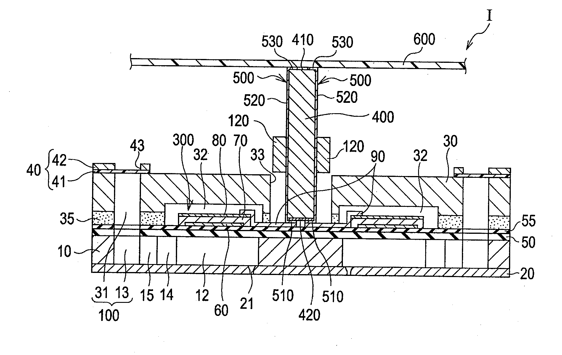
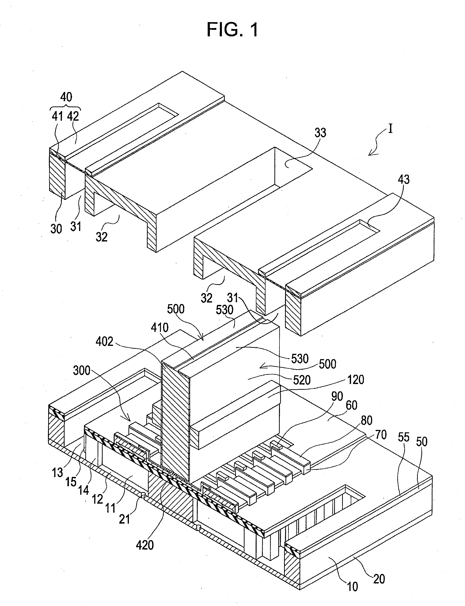
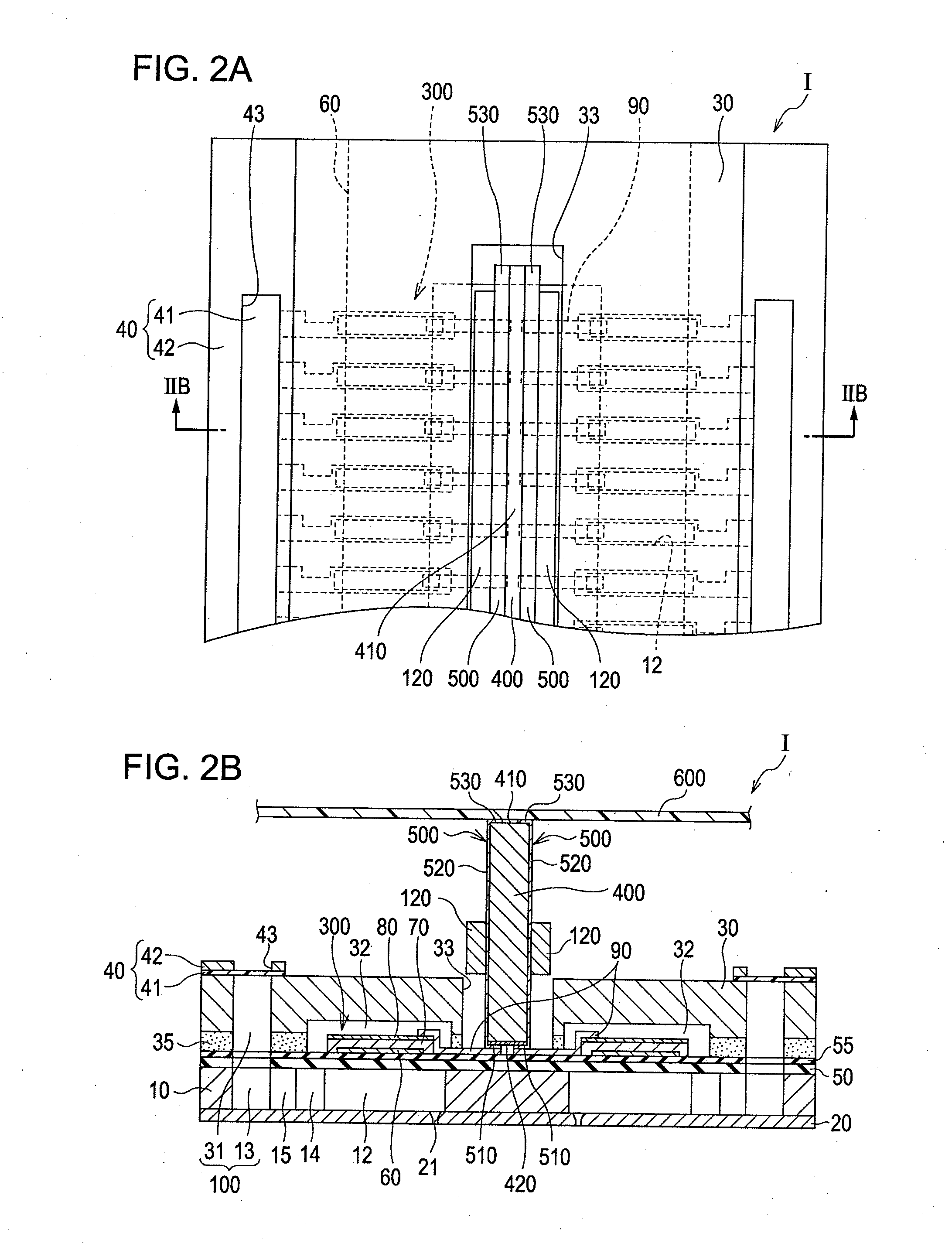
[0032]FIG. 1 is an exploded perspective view schematically illustrating a configuration of an ink jet recording head which is an example of a liquid ejecting head according to a first embodiment of the invention. FIG. 2A is a plan view of FIG. 1, and FIG. 2B is a cross-sectional view taken along a line IIB-IIB of FIG. 2A. Further, in FIG. 1, a flexible printed substrate to be described later is omitted. In addition, FIGS. 3 and 4 are expanded cross-sectional views illustrating a part of the ink jet recording head according to the embodiment.
[0033]A fluid channel formation substrate 10 is made of a silicon single-crystal substrate of a plane orientation (110) in this embodiment, and as shown in the drawing, a silicon dioxide elastic film 50 is formed on one surface thereof.
[0034]In the fluid channel formation substrate 10, plural pressure generating chambers 12 are provided in two columns such that they are provided in parallel with each other in a width direction thereof. In additio...
second embodiment
[0060]FIG. 5 is an enlarged cross-sectional view illustrating the substrate support section of the ink jet recording head according to a second embodiment of the invention. The ink jet recording head according to this embodiment shows a modified example with regard to the substrate support section, and the other portions are the same as those in the first embodiment. Here, the same components as those in the first embodiment are designated by the same reference numerals, and the description already given will be omitted.
[0061]As shown in the drawing, the substrate support section 400A of the ink jet recording head II according to this embodiment is provided such that the area of the connection support surface 411 is formed to be larger than that of the surface of the substrate support section 400A facing the fluid channel formation substrate 10. Specifically, in this embodiment, the length of the connection support surface 411 in the longitudinal direction of the piezoelectric eleme...
third embodiment
[0064]FIG. 6 is an exploded perspective view illustrating the ink jet recording head according to a third embodiment of the invention. FIG. 7A is a plan view illustrating the ink jet recording head shown in FIG. 6. FIG. 7B is a cross-sectional view taken along a line VIIB-VIIB of FIG. 7A. Further, in FIG. 6, the flexible printed substrate is omitted. The ink jet recording head according to this embodiment shows a modified example with regard to the substrate support section, and the other portions are the same as those in the first embodiment. Here, the same components as those in the first embodiment are designated by the same reference numerals, and the description already given will be omitted.
[0065]As shown in the drawing, in the ink jet recording head III according to this embodiment, a positioning convex portion 412 with a predetermined size is provided to protrude from the connection support surface 410, and the positional convex portion 412 is erected and provided on the con...
PUM
 Abstract
Description
Claims
Application Information
 - R&D
- Intellectual Property
- Life Sciences
- Materials
- Tech Scout
- Unparalleled Data Quality
- Higher Quality Content
- 60% Fewer Hallucinations
Browse by: Latest US Patents, China's latest patents, Technical Efficacy Thesaurus, Application Domain, Technology Topic, Popular Technical Reports.
© 2025 PatSnap. All rights reserved.Legal|Privacy policy|Modern Slavery Act Transparency Statement|Sitemap|About US| Contact US: help@patsnap.com