Spin-coated polymer microcavity for light emitters and lasers

a technology of spincoated polymer and light emitter, which is applied in the direction of laser details, optical resonator shape and construction, luminescent compositions, etc., can solve the problems of not being used to develop surface emitters, many layers of high reflectivity, and poor control of periodic structure, so as to achieve low refractive index, poor periodic structure control, and high reflectivity of dbr mirrors

Inactive Publication Date: 2010-04-22
RES FOUND THE CITY UNIV OF NEW YORK
View PDF8 Cites 5 Cited by
  • Summary
  • Abstract
  • Description
  • Claims
  • Application Information

AI Technical Summary

Problems solved by technology

While polymeric microcavities have been fabricated for realizing ultrafast switches, they have not been used for developing surface emitters.
The disadvantages of this existing technology include the need for many layers for high reflectivity of the DBR mirror, poor control of the periodic structure, low contrast of the refractive indices of the dielectric materials, and the requirement for expensive techniques to fabricate the microcavities.

Method used


Image

  • Spin-coated polymer microcavity for light emitters and lasers
  • Spin-coated polymer microcavity for light emitters and lasers
  • Spin-coated polymer microcavity for light emitters and lasers

Examples


Embodiment Construction

Methodology

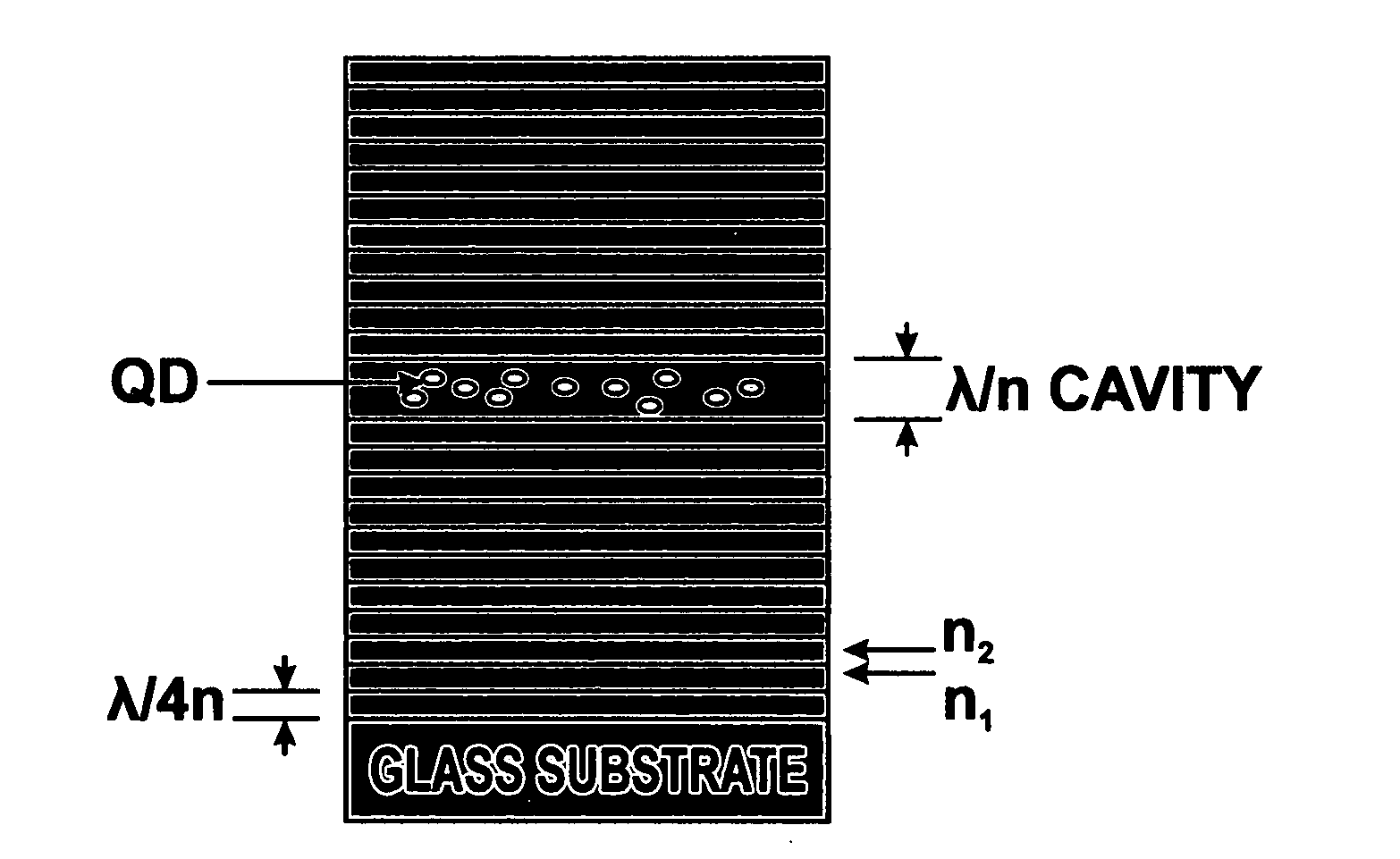
[0023]The one dimensional polymer microcavity structure was fabricated by spin coating polymers of different refractive indices on a glass substrate. The microcavity structure comprises a cavity sandwiched between two Distributed Bragg reflectors (DBRs) as shown in FIG. 1, which is a diagrammatic cross sectional view of the microcavity structure of the embodiments of the present invention. Alternating layers of polymers of two different refractive indices were stacked to form the DBRs. The bottom and top DBRs comprise ten and five periods, respectively.

[0024]To achieve high reflectivity, the polymers for the DBR structures were chosen so that they have a relatively high refractive index ratio. The high and low refractive index polymers chosen were poly-N(vinylcarbazole) (PVK) and poly(acrylic acid) (PAA), with refractive indices of 1.683 and 1.420 at 600 nm, respectively. Another important criterion for choosing these polymers was that the solvent of one polymer does not ...


PUM


Abstract

A spin-coated polymer microcavity for light emitters and lasers producing enhancement of spontaneous emission rate from colloidal CdSe / ZnS core / shell quantum dots embedded in a one dimensional polymer microcavity structure at room temperature. The polymer microcavity structures are fabricated using spin coating. Alternating layers of polymers of two different refractive indices were stacked to form the Distributed Bragg reflectors (DBRs). To achieve high reflectivity, the polymers for the DBR structures were chosen so that they have a relatively high refractive index ratio. The high and low refractive index polymers chosen were poly-N(vinylcarbazole) (PVK) and poly acrylic acid (PAA), with refractive indices of 1.683 and 1.420 at 600 nm, respectively. Thin films of quarter wavelength thickness of the two polymers are alternately spin coated on a glass substrate to make the DBR structures. Greater than 90% reflectivity is obtained using ten periods of the structure. A PVK cavity layer of λ thickness embedded with CdSe / ZnS core / shell quantum dots is sandwiched between two of these DBRs to form the entire microcavity structure. The bottom and top DBRs comprise ten and five periods, respectively.

Description

BACKGROUND OF THE INVENTION[0001]1. Field of the Invention[0002]The embodiments of the present invention relate to a spin-coated polymer, and more particularly, the embodiments of the present invention relate to a spin-coated polymer microcavity for light emitters and lasers.[0003]2. Description of the Prior ArtSpin Coating[0004]Spin coating is a known process for forming a layer of dispensed material on a rotating surface using the centrifugal force on the dispensed material. Typically, a substrate is held in a chuck, with a surface-to-be-coated in a horizontal orientation. The chuck then spins causing the surface-to-be-coated to rotate at a predetermined speed, and a dispenser then dispenses a predetermined amount of coating material in liquid form close to the center of the rotation.[0005]The rotation imposes a centrifugal force on the coating material forcing the mass of coating material to be pushed outwards away from the center of rotation towards the edges of the surface to b...

Claims


Application Information

Patent Timeline
Patent Type & Authority Applications(United States)
IPC IPC(8): H01S3/08
CPCC09K11/02C09K11/565C09K11/88C09K11/883H01S3/178H01S3/0621H01S3/0627H01S3/169H01S3/0612
Inventor MEMON, VINOD M.VALAPPIL, NIKESH V.
Owner RES FOUND THE CITY UNIV OF NEW YORK
Why Eureka
Try Eureka