
Computer system and configuration management method therefor

a computer system and configuration management technology, applied in the field of computer systems, can solve the problems of affecting the operation of the computer system, affecting the operation of the server, and the difficulty of the server administrator to quickly change the server configuration, so as to reduce the number of processing steps and a long period of tim

Inactive Publication Date: 2010-04-22
HITACHI LTD
View PDF11 Cites 38 Cited by
  • Summary
  • Abstract
  • Description
  • Claims
  • Application Information

AI Technical Summary

Benefits of technology

The invention allows a server administrator to manage the connections between a server, network, and storage without needing the intervention of a network administrator or storage administrator. This reduces the number of steps and time required to construct and change the computer system's configuration.

Problems solved by technology

Therefore, the construction of the computer system and the configuration change thereof take a large number of processing steps and a long period of time.
The above-mentioned situation causes such a significant problem that a load rapidly increases particularly on tasks running on the computer system in a case of promptly constructing an execution environment for an OS and an application.
This leads to a problem that it is difficult for the server administrator to promptly change the server configuration.

Method used


Image

  • Computer system and configuration management method therefor
  • Computer system and configuration management method therefor
  • Computer system and configuration management method therefor

Examples


first embodiment

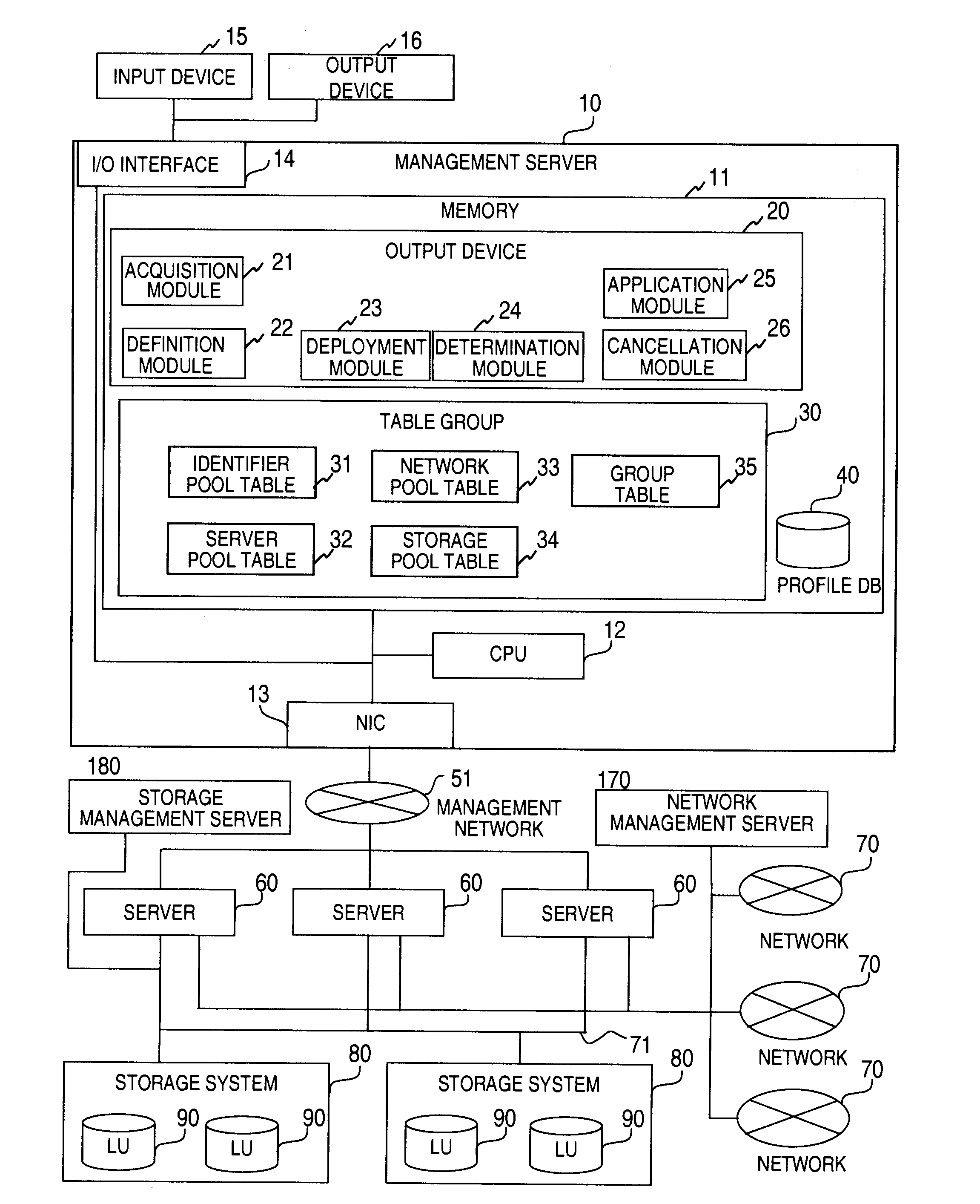
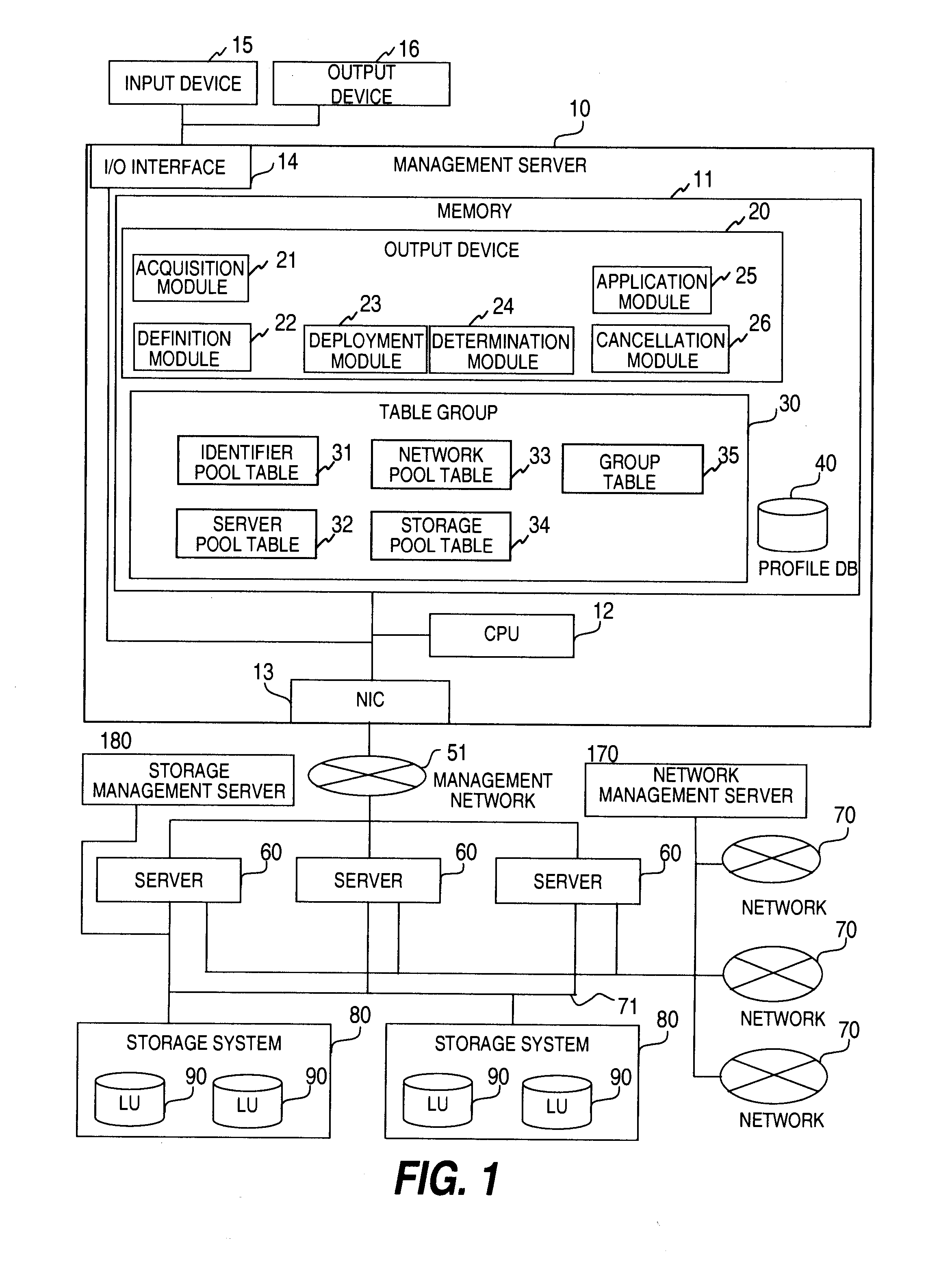
[0042]FIG. 1 is a block diagram illustrating a configuration of a computer system according to a first embodiment. The computer system according to this embodiment includes a management server 10, an input device 15, an output device 16, a management network 51, at least one server 60, at least one network 70, at least one storage system 80, and a storage area network (SAN) 71 for coupling the at least one server 60 with the at least one storage system 80. Further, the storage system 80 includes at least one logical unit (LU) 90. Here, the LU 90 represents a logical disk. The management server 10 includes a memory 11 that holds a configuration management program 20, a table group 30, and a profile DB 40. The at least one network 70 has communication paths therefore managed by a network management server 170. The SAN 71 and the at least one storage system 80 have access paths therefor managed by a storage management server 180.

[0043]The management server 10 includes a network interfa...

second embodiment

[0101]In the first embodiment, description has been made of the case where the server 60 included in the computer system can be coupled any of the networks 70 and any of the storage systems 80. In a second embodiment, description is made of a case where there exist the network 70 and the storage system 80 to which the server 60 included in the computer system cannot be coupled.

[0102]In this embodiment, the server pool table 32 illustrated in FIG. 6 needs to hold connection destination information for the server, which is indicated by a column 324. The column 324 holds information on the network 70 and the storage system 80 to which the server 60 indicated by the column 321 can be coupled. For example, a case where the storage systems 80 to which HBA 1 can be coupled are Storage System 1 and Storage System 2 is described as “HBA1:Storage System 1,Storage System 2”.

[0103]FIG. 22 is a flowchart of a processing performed as a network pool candidate search 2401 according to this embodime...

third embodiment

[0107]In the first and second embodiments, the case of configuring the computer system has been described with regard to all of the servers 60, the networks 70, and the storage systems 80 that are included in the computer system. In a third embodiment, according to the user, the case of changing the configuration of the computer system is described with regard to parts of the servers 60, the networks 70, and the storage systems 80 that are included in the computer system.

[0108]In this embodiment, it is necessary for the table group 30 illustrated in FIG. 1 to include a group table 35 of FIG. 9 for holding the user and group information.

[0109]In this embodiment, the information on the group indicated by the column 325 is required in the server pool table 32 illustrated in FIG. 6. The column 325 holds an identifier of a group to which the server 60 indicated by the column 321 belongs. It should be noted that one of the servers 60 may belong to a plurality of groups. In that case, the ...


PUM


Abstract

Provided is a computer system that requires only a server administrator for construction thereof and configuration change thereof. A management server acquires connection destination interface identifiers set for external apparatuses, stores the connection destination interface identifiers into a first table, acquires specifications of server computers and identifiers of the server computers, stores the specifications and the identifiers into a second table, acquires specifications of external apparatuses, stores the specifications into the first table, receives a profile to be deployed onto one of the server computers, acquires a server computer satisfying the profile from the second table, acquires an external apparatus satisfying the profile from the first table, acquires a connection destination interface identifier from the first table, and notifies the server computer acquired from the second table of the acquired interface identifier, and the server computer updates an interface identifier of an interface by the received interface identifier.

Description

CLAIM OF PRIORITY[0001]The present application claims priority from Japanese patent application JP2008-267541 filed on Oct. 16, 2008, the content of which is hereby incorporated by reference into this application.BACKGROUND OF THE INVENTION[0002]This invention relates to a computer system, in particular, a configuration management method of managing connections among a server, a network, and a storage.[0003]The computer system is configured by physically coupling the server, the network, and the storage with one another by wire. However, in order to flexibly operate the computer system, it is desirable that the connections among the server, the network, and the storage can be flexibly changed.[0004]Conventional technologies for realizing such a computer system include a technology of constructing a virtual network group in a network (for example, MAC-based VLAN) and a technology of constructing a logical disk system from a disk array provided to a storage system (see, for example, U...

Claims


Application Information

Patent Timeline
Patent Type & Authority Applications(United States)
IPC IPC(8): G06F15/177
CPCG06F13/00G06F15/177G06F13/10H04L41/085
Inventor HATASAKI, KEISUKETAKAMOTO, YOSHIFUMI
Owner HITACHI LTD
Learn More