Fluid filled type vibration damping device

a technology of vibration damping and fluid filling, which is applied in the direction of shock absorbers, machine supports, mechanical devices, etc., can solve the problems of limiting the angle of inclination of the principal elastic axis, not providing a wholly satisfactory solution, and difficult to ensure sufficient durability of the component, so as to achieve the effect of ensuring durability and diffusing spring characteristics

Active Publication Date: 2010-04-29
SUMITOMO RIKO CO LTD
View PDF9 Cites 26 Cited by
  • Summary
  • Abstract
  • Description
  • Claims
  • Application Information

AI Technical Summary

Benefits of technology

[0010]It is therefore one object of the present invention to provide a fluid filled type vibration damping device of novel structure adapted to impart the elastic rubber body with greatly differing spring characteristics in two mutually orthogonal axis-perpendicular directions, yet able to ensure durability on the part of the elastic rubber body.

Problems solved by technology

However, the fluid filled type vibration damping devices disclosed in Japanese Patent No. 4039827 and U.S. Pat. No. 6,349,927 do not provide a wholly satisfactory solution.
However, where the elastic rubber body has been thinned through formation of pocket portions in this way, it has proven difficult to ensure sufficient durability of the component while at the same time achieving the desired spring ratio in the vehicle lengthwise direction versus the vehicle lateral direction.
However, where localized thinning of the elastic rubber body has been accomplished exclusively through indentation of the elastic rubber body along its inner circumference, the angle of incline of the principal elastic axis will be limited by the angle of incline of the surface of the elastic rubber body.
As a result, considerable thinning of the elastic rubber body will be necessary in order to achieve the desired spring ratio in two axis-perpendicular directions, making it difficult to concomitantly achieve adequate durability.
As a result, stress concentrations tended to form in boundary sections between thin portions and thick portions, so reduced durability of the elastic rubber body was a problem.
If on the other hand the thin portions of the elastic rubber body are made thicker with a view to ensuring sufficient durability of the elastic rubber body, it becomes difficult to achieve the desired spring ratio in the vehicle lengthwise direction versus the vehicle lateral direction.

Method used


Image

  • Fluid filled type vibration damping device
  • Fluid filled type vibration damping device
  • Fluid filled type vibration damping device

Examples


first embodiment

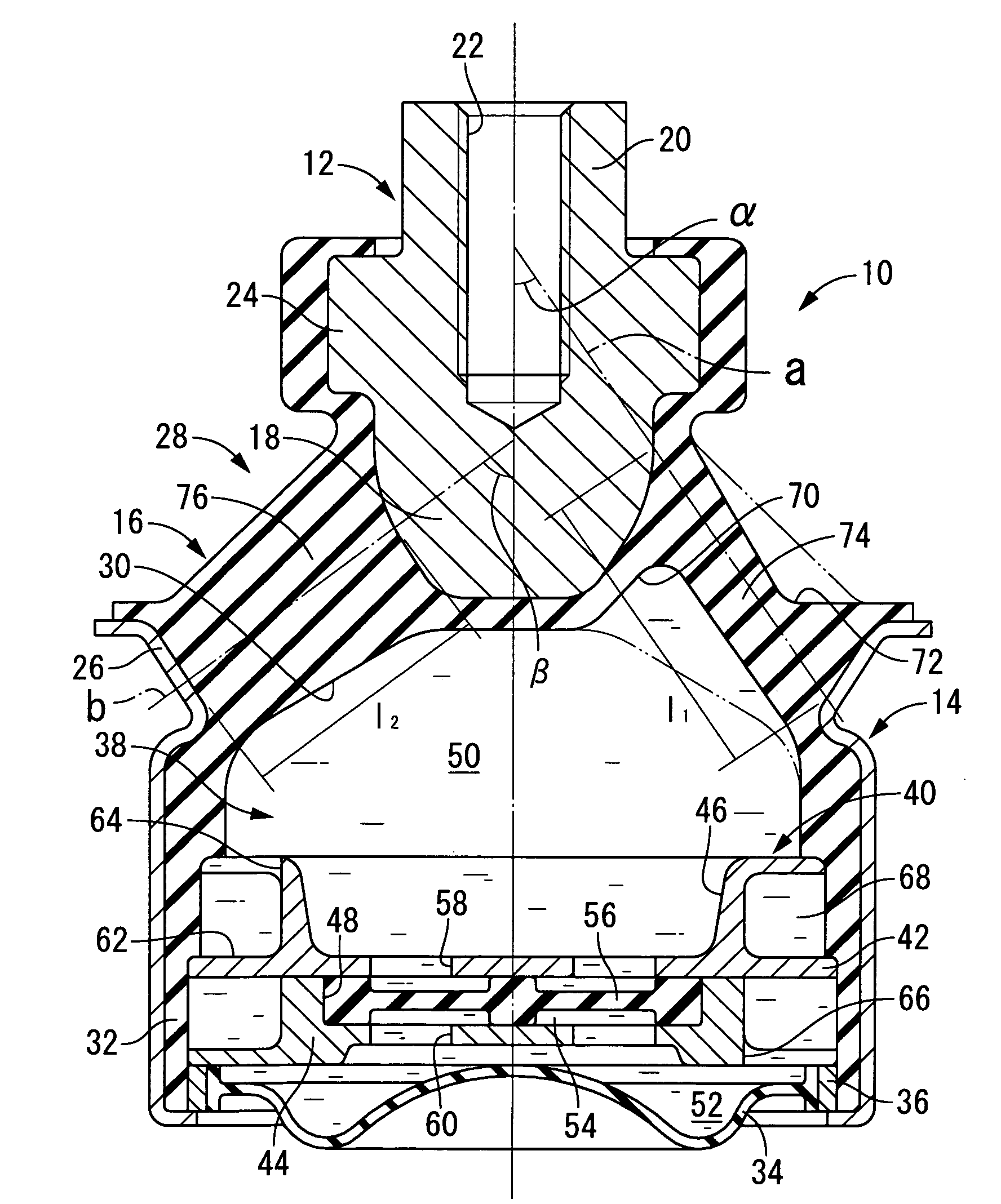
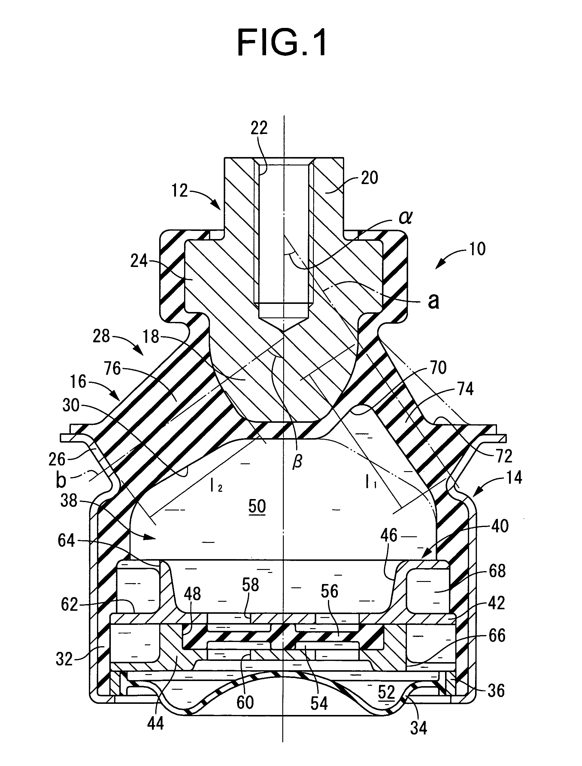
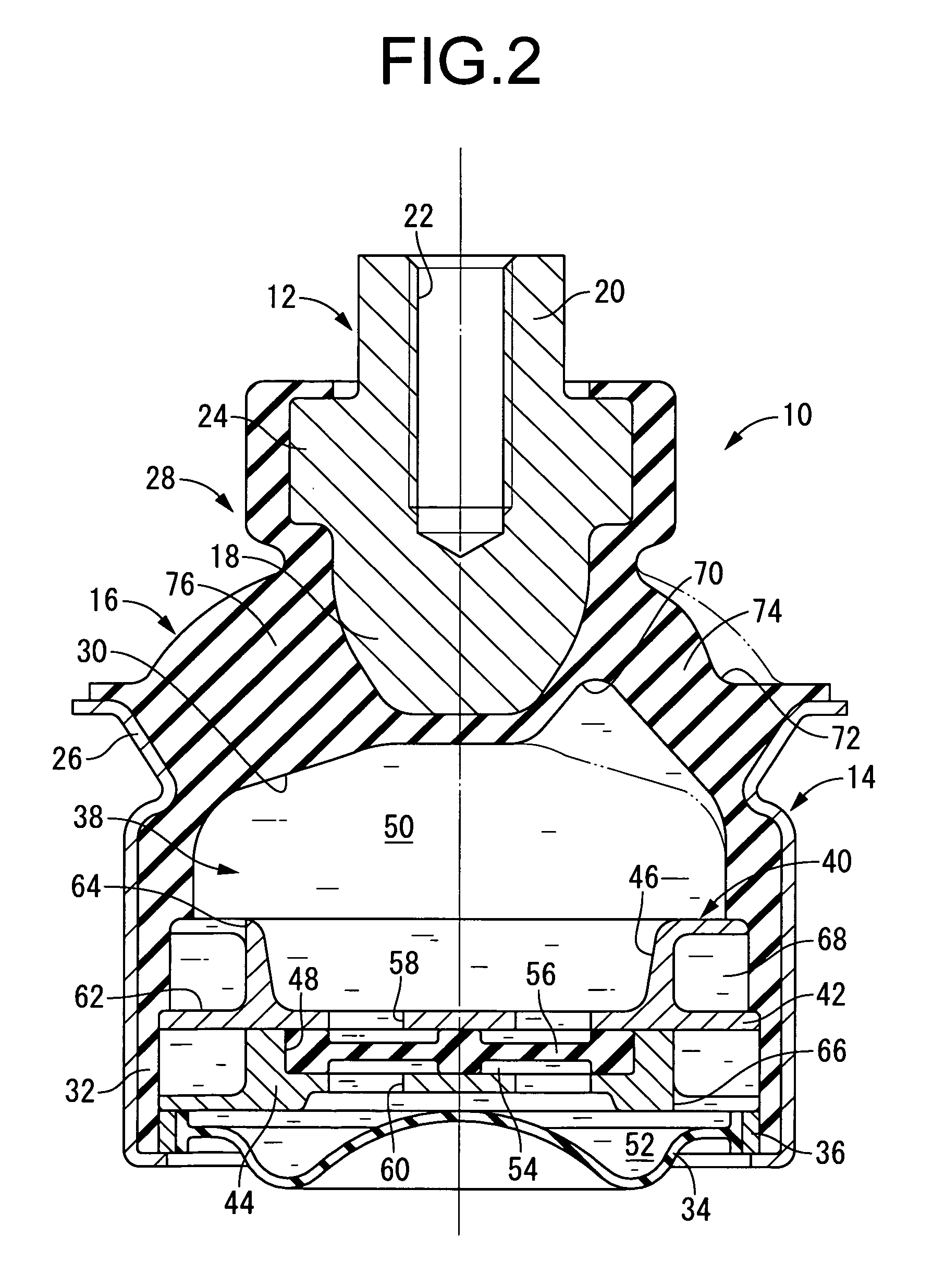
[0043]Referring first to FIGS. 1 and 2, there is depicted an automotive engine mount 10 as the fluid filled type vibration damping device of construction according to the present invention. The engine mount 10 has a construction in which an inner shaft member 12 of metal and an outer tube member 14 of metal are connected to one another by an elastic rubber body 16. The inner shaft member 12 is then mounted onto the power unit side (not shown) while the outer tube member 14 is mounted onto the vehicle body side (not shown), whereby the engine mount 10 is interposed between the power unit and the vehicle body in such a way as to provide vibration damped linkage of the power unit to the vehicle body. In the description hereinbelow, the vertical direction refers to the vertical direction in FIG. 1, which is also the principal direction of vibration input as well as the axial direction. In FIG. 1, the engine mount 10 is depicted in isolation prior to installation in a vehicle; in FIG. 2,...

third embodiment

[0085]Next, FIG. 7 depicts an automotive engine mount 86 as the fluid filled type vibration damping device according to the present invention. In this engine mount 86, outside face recesses 88 are formed on the elastic rubber body 16.

[0086]The outside face recesses 88 are formed so as to open onto the outside peripheral face of the elastic rubber body 16. As shown in FIG. 7, according to the present embodiment, the outside face recesses 88 are recessed in the axial direction so as to indent the elastic rubber body 16 in the axial direction. Specifically, in the outside face recesses 88, the inside peripheral section of the base wall slopes downward towards the outside peripheral side; the outside peripheral section of the base wall slopes upward towards the outside peripheral side; and the deepest part of each outside face recess 88 is situated axially below the inside peripheral edge and outside peripheral edge of the outside face recess 88. In the present embodiment in particular,...


PUM


Abstract

A fluid filled type vibration damping device including an elastic rubber body elastically connecting an inner shaft member and an outer tube member. The elastic rubber body has a solid rubber wall that includes inside face recesses and outside face recesses respectively formed to either side of the inner shaft member in an axis-perpendicular direction so that a pair of thin portions and a pair of thick portions respectively situated in opposition along mutually orthogonal axes lying in axis-perpendicular directions are formed in the solid rubber wall. A deepest part of the inside face recesses is situated towards an axial small diameter side of the solid rubber wall with respect to an deepest part of the outside face recesses, with the inside face recesses and the outside face recesses overlapping one another in the axis-perpendicular direction of the solid rubber wall.

Description

INCORPORATED BY REFERENCE[0001]The disclosure of Japanese Patent Application No. 2008-276445 filed on Oct. 28, 2008 including the specification, drawings and abstract is incorporated herein by reference in its entirety.BACKGROUND OF THE INVENTION[0002]1. Field of the Invention[0003]The present invention relates generally to a vibration damping device adapted to be interposed between members that make up a vibration transmission system in order to provide vibration damped linkage and / or vibration damped support to these members; and relates in particular to a fluid filled type vibration damping device that utilizes vibration damping action based on the flow action of a non-compressible fluid filling the interior.[0004]2. Description of the Related Art[0005]There are a number of known vibration damping devices designed to be interposed between members that make up a vibration transmission system in order to provide vibration damped linkage and vibration damped support to the members t...

Claims


Application Information

Patent Timeline
Patent Type & Authority Applications(United States)
IPC IPC(8): F16F13/00
CPCF16F13/108
Inventor OKUMURA, KEIMATSUOKA, NORITAKA
Owner SUMITOMO RIKO CO LTD
Why Eureka
Try Eureka