
Power Generator

Inactive Publication Date: 2010-04-29
PACER TURBINES
View PDF20 Cites 24 Cited by
  • Summary
  • Abstract
  • Description
  • Claims
  • Application Information

AI Technical Summary

Benefits of technology

[0010]It is therefore an object of the present invention to provide a turbine apparatus and / or a method of manufacturing a turbine apparatus which will go at least some way towards overcoming the above disadvantages or which will at least provide the public with a useful choice.
[0052]Preferably, the main rotor and the generator rotor are each provided with split bearings mountable about the flexible line to thereby allow the main rotor and generator rotor to rotate freely with respect to a flexible line to which the turbine apparatus it is connected.
[0069]Preferably, the main rotor has a helical structure to reduce load on its bearing(s).

Problems solved by technology

Sources of power, such as fossil fuels and batteries are respectively increasingly expensive and have limitations in terms of their weight and environmental concerns.
Solar cells are another alternative source of portable power although they are commonly fragile, physically large, expensive and require orientation to the sun for maximum efficiency.
Wind energy extraction on a small scale also has limitations.
1. Horizontal axis (propeller) types which are usually mounted rigidly on a pole. Turbines of this type are usually noisy, hazardous to bystanders and take up a large amount of space as the propeller requires orientation into the wind with a vane.
2. Vertical axis wind generators are less common but are once again rigidly mounted, on a tower or bracket and are generally individually fabricated rather than mass-produced. The rotors usually have at least two (usually two or three) identical semi-cylindrical blades or vanes which rotate about a vertical axis. Neighbouring vanes may be connected together or to a central shaft. Alternatively, the inner edges of the vanes may be overlapped to allow the driving fluid to exit a first vane and then pass into a further vane to do further useful work.
Savonius-type rotors are self-starting however they mostly rely on drag to produce rotation and so are unable to generate blade tip speeds much greater than the driving wind speed.
They are also relatively inefficient at converting available wind energy into electrical energy.
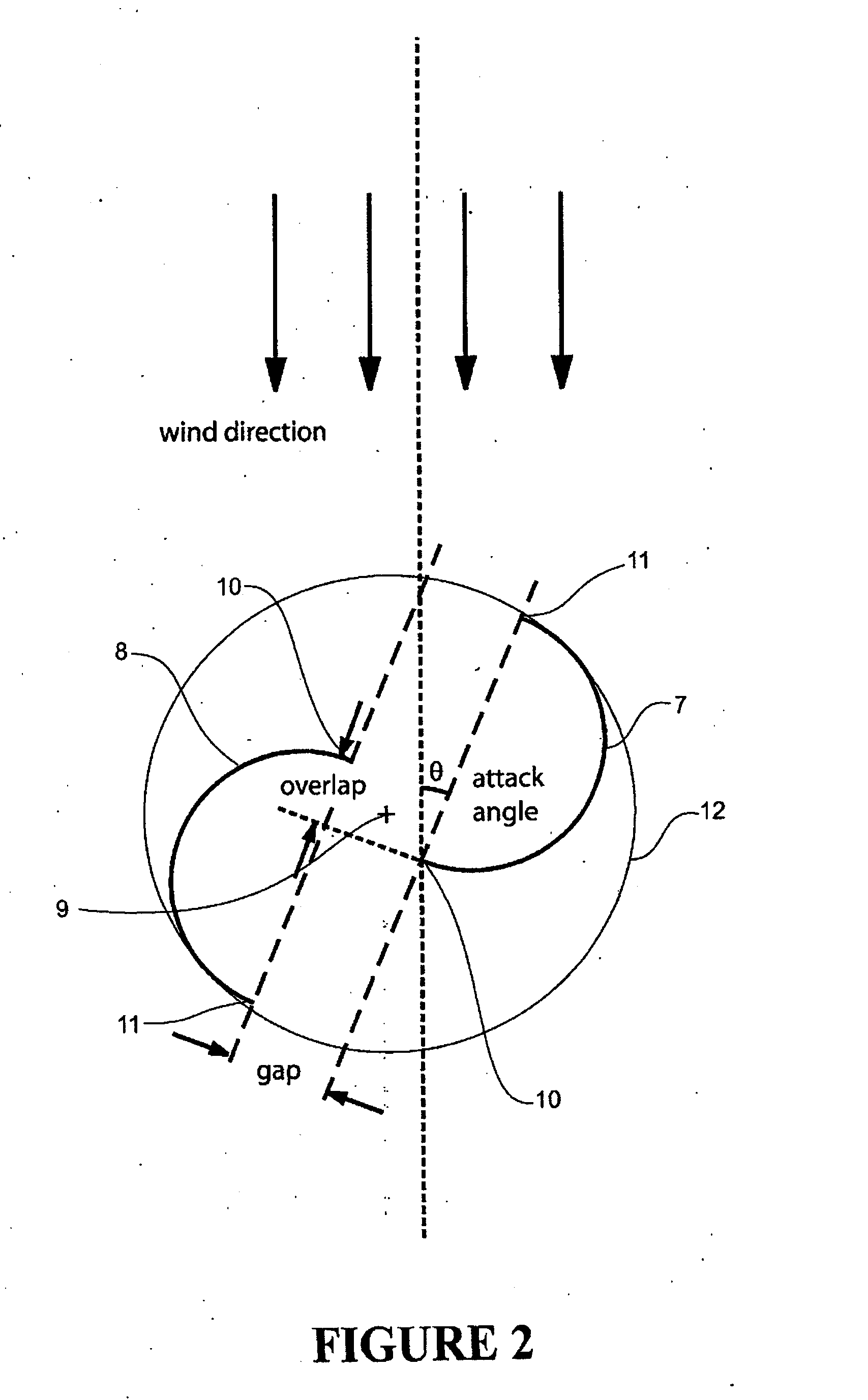
Savonius-type rotors are also inherently unbalanced due to the torque produced varying widely with the attack angle of the blade relative to the wind during the rotation cycle.
This results in mechanical vibrations in the turbine requiring strengthened support structures, and causes power losses due to parasitic vibrations, increased friction in the bearings, and bearing wear and failure.
However, the above differences accentuate the unbalanced nature of the Savonius design.
However, helical blades are more expensive to fabricate than non-helical blades and are not generally capable of cost-efficient moulding techniques such as a single transitional mould release or simple two-part “straight-pull” dies.
To minimise eccentric rotation of the shaft due to the aforementioned imbalance, existing vertical axis wind turbines usually have low aspect ratios (rotor height to width) resulting in an undesirable somewhat squat appearance to the turbine.
Because of the above limitations, vertical axis wind turbines have not been capable of mass production and existing turbines are not generally portable (that is, easily movable and not requiring permanent mounting) and suitable for low power (say under 3 kW) consumer purposes such as trickle charging batteries.
However, the rotor cross-section profiles disclosed are inefficient with regard to the proportion of available wind energy that they can extract.
Improved balance is attempted by increasing the number of blades per rotor which increases the complexity and therefore difficulty of manufacture.
Furthermore, because of the lack of blade overlap, the rotors are inefficient and have a stall position that hinders starting in low wind conditions.
Also, the wind turbine disclosed requires either replacement of a section of the stay or integration into a stay at the design stage and no retrofitting option that leaves the stay intact is disclosed.
The aforementioned disadvantages of non-overlapping blades and the inherent imbalance and low speed capabilities of the Savonius-type rotors also apply to the turbine disclosed in WO9008881A.

Method used


Image

  • Power Generator
  • Power Generator
  • Power Generator

Examples


first embodiment

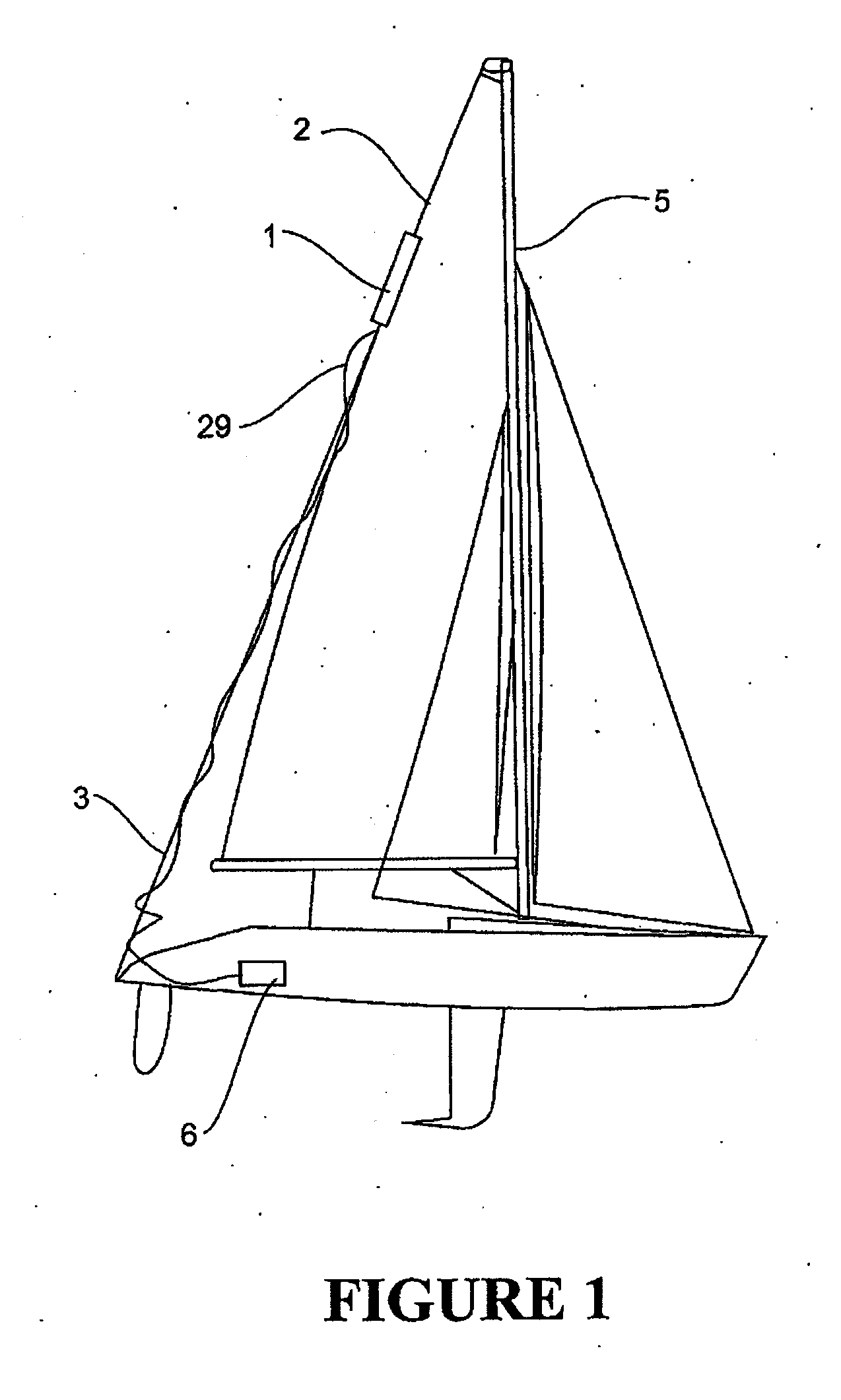
[0111]With reference in particular to FIG. 1, a turbine apparatus 1 according to the present invention is shown. The turbine apparatus is portable (in that it is small, lightweight and easily moved from one place to another) and has an elongated shape including a part which rotates about a longitudinal axis in response to movement of a fluid such as water or more preferably wind. The turbine apparatus is therefore of the type generally referred to as a longitudinal or vertical axis wind turbine. As will be explained below, it is thought to be particularly advantageous to mount turbine 1 flexibly or non-rigidly such as by attaching the longitudinal ends to cables or ropes 2,3 which are slightly tensioned. As will be explained below, the turbine could be attached around a single cable or rope.

[0112]A use of the turbine 1 is in the generation of electricity to power consumer electronic devices having relatively low power requirements. As seen in FIG. 1, it is anticipated that the turbi...

second embodiment

[0135]FIGS. 9A-14B show the invention. This embodiment of the invention is similar to that described in relation to FIGS. 1-8 and can be used in the same manner, although there are some differences in the generator arrangement. As can be seen in FIGS. 9A-9C the general shape of the main rotor is the same as that described in relation to FIGS. 3A-3B. As can be seen in FIG. 9C, cross-sections A and C of the rotor 13 are shown with the bridging sections 17. In FIG. 9C, the bridging sections are shown abutting each other indicating the actual manner in at which the two blade sections will be arranged. As noted earlier in relation to FIG. 3C, the bridging sections are shown in a spaced apart arrangement. FIG. 9C also shows the rotor 90 and armature 91 of the generator 92 that are housed in the bottom bulb 23 of the main rotor 13. FIG. 10A shows the generator 92 in more detail.

[0136]Only the differences, which relate to the generator 92, will be described here. All other aspects of the se...


PUM

PropertyMeasurementUnit
Lengthaaaaaaaaaa
Angleaaaaaaaaaa
Poweraaaaaaaaaa

Abstract

The present invention relates to a vertical axis turbine 1 apparatus for converting movement of a fluid into electrical power and a method of manufacture of a turbine. The turbine can be installed on a flexible line 2, such as a cable, rope or stay. It could be used on the stay of a yacht. The main rotor 13, 14 of the turbine has least two helical blades arranged about the longitudinal axis with rotational symmetry, the blades being substantially identical in shape and having a lift-producing cross-sectional shape at least along a part of their longitudinal length. A generator 22 coupled to the main rotor 13, 14 and is contained in a generator housing 23.

Description

FIELD OF THE INVENTION[0001]This invention relates to power generators and in particular, though not solely, to electrical power generators using wind turbines and more particularly to portable low power and low cost longitudinal (such as vertical) axis wind turbines used for trickle charging batteries or directly powering electronic devices.BACKGROUND OF THE INVENTION[0002]Miniaturisation and mass manufacture of portable electronic devices have created a demand for portable power. Sources of power, such as fossil fuels and batteries are respectively increasingly expensive and have limitations in terms of their weight and environmental concerns. Solar cells are another alternative source of portable power although they are commonly fragile, physically large, expensive and require orientation to the sun for maximum efficiency.[0003]Wind energy extraction on a small scale also has limitations. Low power wind generators, under say 3 kW, are commonly of two types:[0004]1. Horizontal axi...

Claims


Application Information

Patent Timeline
IPC IPC(8): F03D9/00B23P11/00F03D3/06F03D11/04
CPCY10T29/49316F03D3/061F05B2240/213F03D9/002Y02E10/74F05B2250/25F03D9/11F03D9/25F03D9/32F03D13/20Y02E10/728Y02E70/30Y02P70/50
Inventor BOYD-WILSON, PETERBINNER, PAUL
Owner PACER TURBINES
Learn More