Hybrid working machine

a hybrid working machine and working machine technology, applied in the field of hybrid working machines, can solve problems such as the inability to normally perform regenerative brake operation

Active Publication Date: 2010-04-29
KOBELCO CONSTR MASCH CO LTD
View PDF25 Cites 20 Cited by
  • Summary
  • Abstract
  • Description
  • Claims
  • Application Information

AI Technical Summary

Benefits of technology

[0011]It is an object of the present invention to provide a hybrid working machine that ensures both the stable rotation and hydraulic operation thereof even when an electric storage device is unusable.
[0013]Accordingly, when the electric storage device is unusable, the power consumption of the rotation motor is suppressed while the voltage of the direct current bus is maintained greater than or equal to the normal operation voltage of the system. Therefore, both stable rotation and hydraulic operation can be ensured.
[0015]In such a case, it is preferable that the hybrid working machine according to the aspect of the present invention further include a regenerative resistor that consumes regenerative power when the rotation motor is performing a regenerative operation; and a regenerative-resistor controller that controls the regenerative resistor. In this way, the regenerative power generated when the rotation speed is decreasing is consumed by the regenerative resistor, and a regenerative brake operation can be normally performed.

Problems solved by technology

However, when the electric storage device becomes unusable, there will be no storage device for the regenerative power, and a regenerative brake operation may not be normally performed.

Method used


Image

  • Hybrid working machine
  • Hybrid working machine
  • Hybrid working machine

Examples


Embodiment Construction

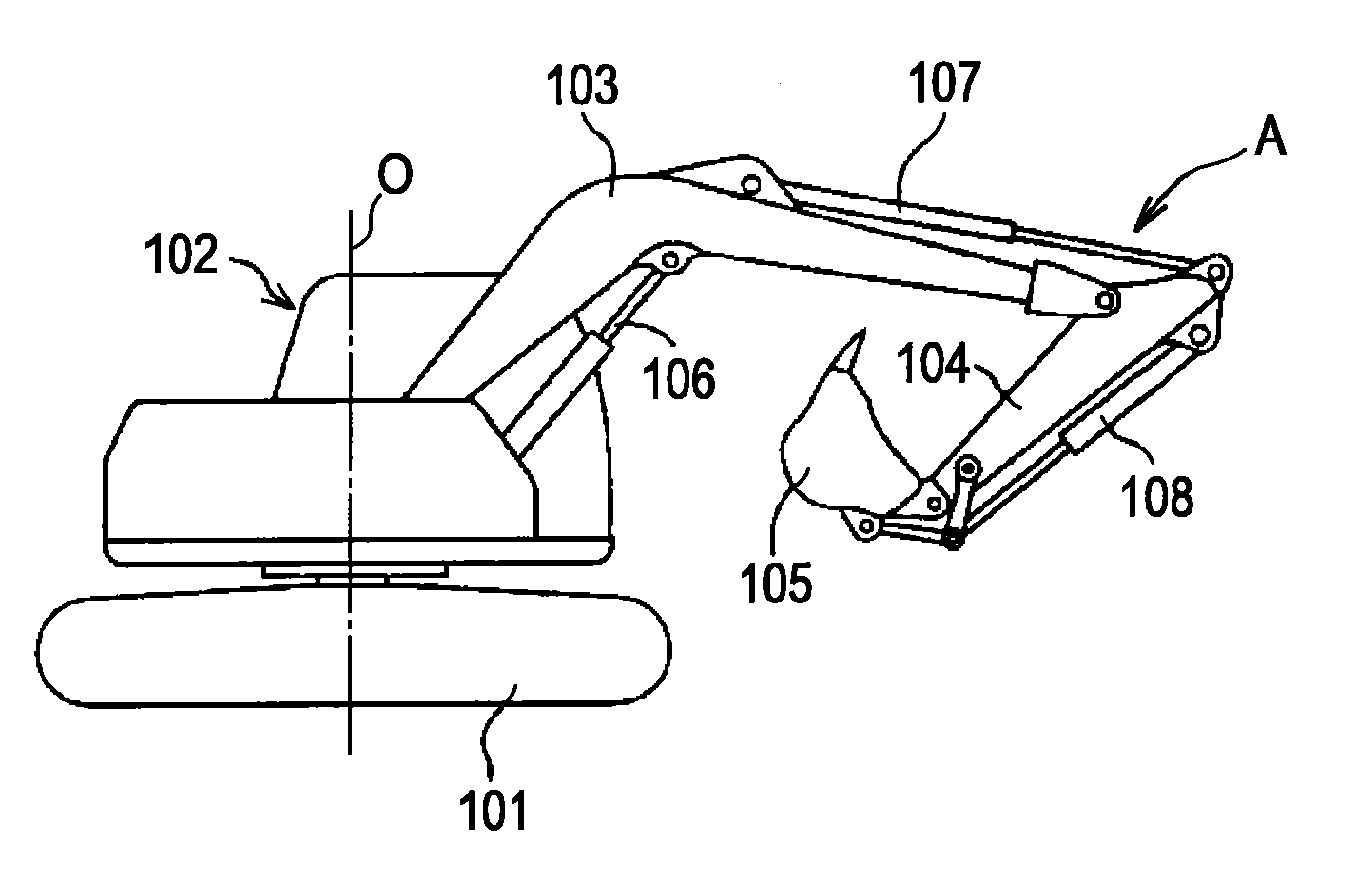
[0022]A hybrid excavator will be described as embodiments of the present invention.

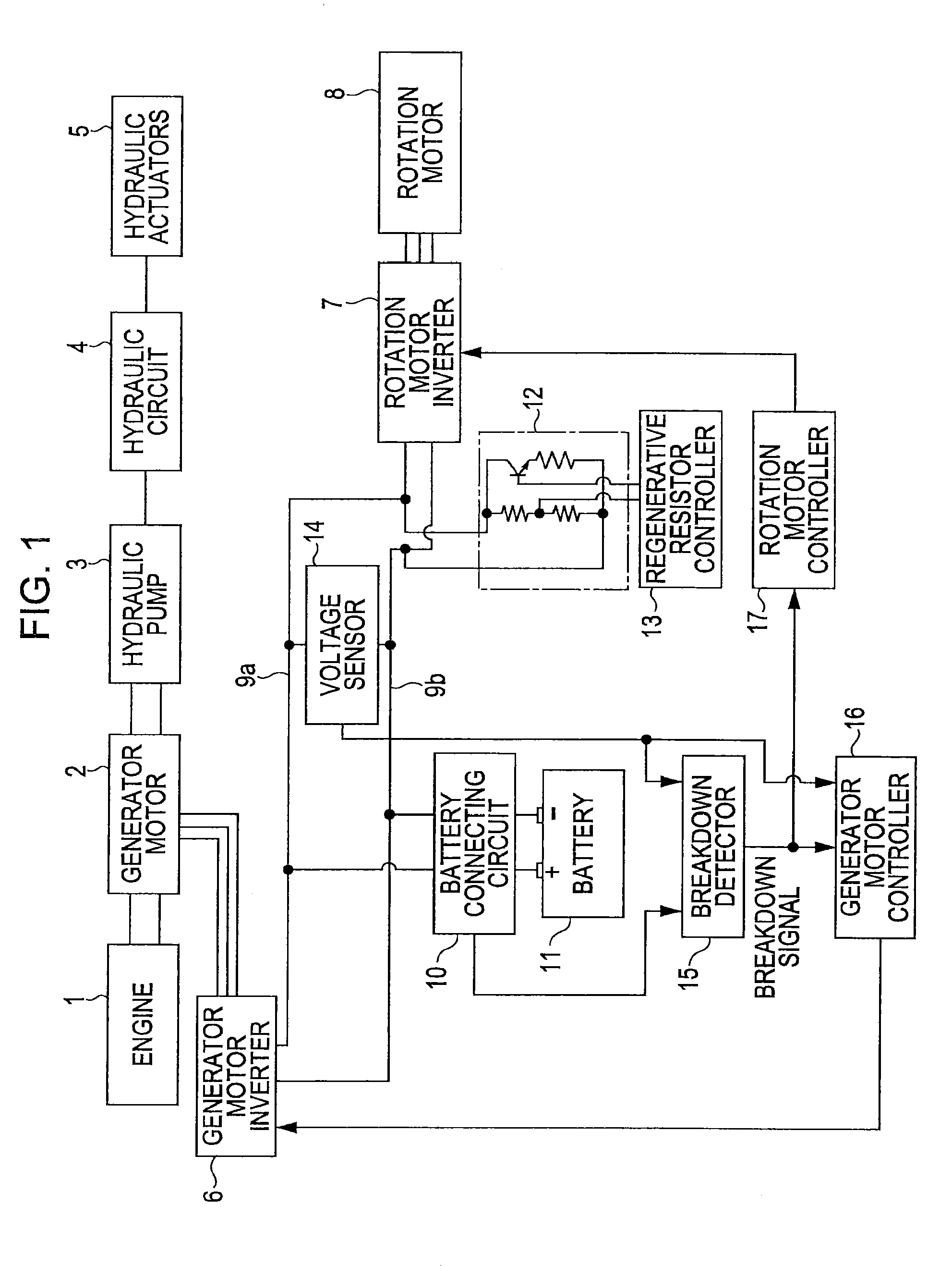
[0023]FIG. 1 is a block diagram of a drive system and a control system.

[0024]As illustrated in FIG. 1, a generator motor 2 that performs both a generator operation and a motor operation and a hydraulic pump 3 are connected to an engine 1 serving as a power source. The generator motor 2 and the hydraulic pump 3 are driven by the engine 1.

[0025]A boom cylinder and other hydraulic actuators (which are collectively given the reference numeral 5) are connected to the hydraulic pump 3 via a hydraulic circuit 4 including control valves (not shown). The hydraulic actuators 5 are driven by pressure oil supplied from the hydraulic pump 3.

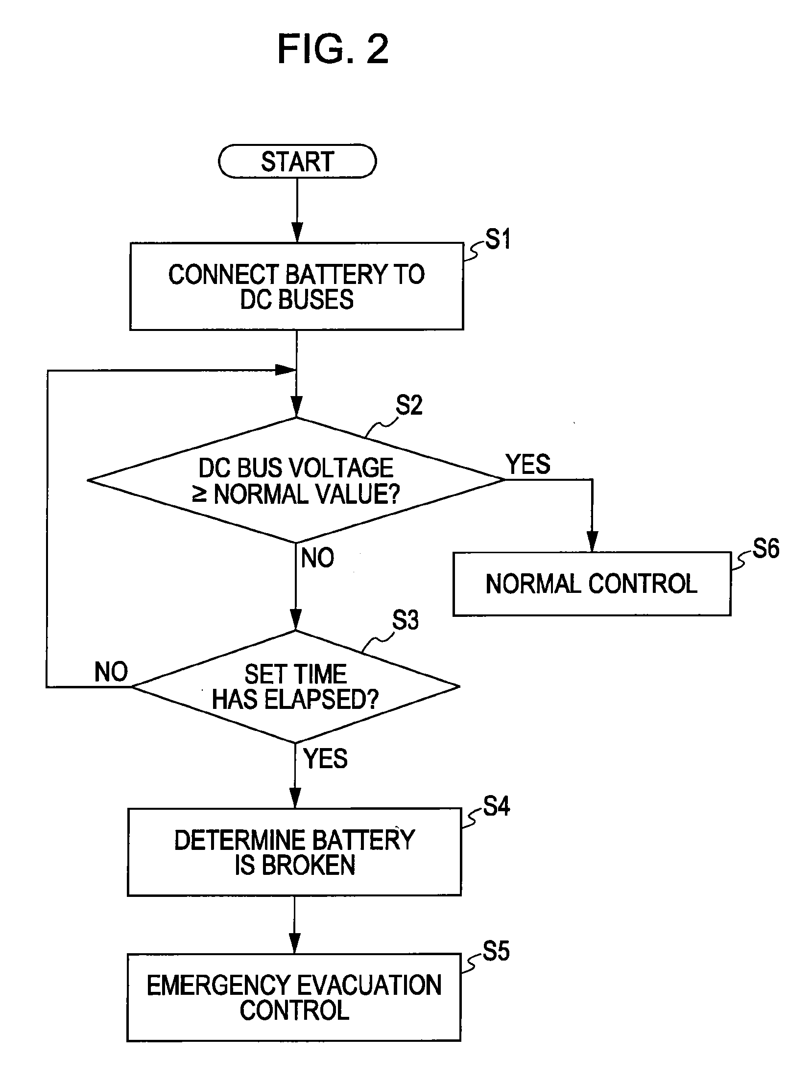
[0026]In contrast, a rotation motor 8 is connected to the generator motor 2 via a generator motor inverter 6 and a rotation motor inverter 7 constituting a controller unit. A battery (electric storage device) 11 is connected via a battery connecting circuit 10 to DC buses 9a an...


PUM


Abstract

In a hybrid excavator, a generator motor and a hydraulic pump are driven by using an engine as a power source. A battery is charged with power generated by the generator motor. A rotation motor is driven by the generator motor and the battery. The voltage of a DC bus is detected by a voltage sensor, and whether the battery is unusable is determined by a breakdown detector. When the battery becomes unusable, emergency evacuation control is performed so that the power consumption of the rotation motor will be suppressed to be less than or equal to the power generation of the generator motor while maintaining the DC bus voltage greater than or equal to the normal operation voltage of the system.

Description

BACKGROUND OF THE INVENTION[0001]1. Field of the Invention[0002]The present invention relates to a hybrid working machine that uses both engine power and electric power.[0003]2. Description of the Related Art[0004]The related art will be described using an excavator by way of example.[0005]As illustrated in FIG. 4, an excavator includes a crawler-type lower traveling structure 101 and an upper rotating structure 102 rotatably mounted, around a vertical shaft O, on the lower traveling structure 101. A working attachment A is mounted on the upper rotating structure 102.[0006]The working attachment A includes a boom 103 capable of moving up and down, an arm 104 attached to the tip of the boom 103, a bucket 105 attached to the tip of the arm 104, and cylinders 106, 107, and 108 that are hydraulic actuators for driving the boom 103, the arm 104, and the bucket 105, respectively.[0007]For a hydraulic excavator, a rotation hydraulic motor is used as a rotation actuator for rotating the upp...

Claims


Application Information

Patent Timeline
Patent Type & Authority Applications(United States)
IPC IPC(8): H02P7/00H02P3/12B60K6/46E02F9/20H02P27/06
CPCB60K6/46Y02T10/7077B60L1/20B60L7/02B60L7/10B60L11/123B60L2200/40B60W10/06B60W10/08B60W10/26B60W20/00B60W2510/244E02F9/2025E02F9/2075Y02T10/6208Y02T10/6217Y02T10/6282Y02T10/6286Y02T10/7005B60L1/003B60W20/50B60W2050/0297B60W2300/17B60Y2200/412B60L50/61E02F9/123E02F9/2091Y02T10/62Y02T10/70B60W10/04Y02T10/7072
Inventor KAGOSHIMA, MASAYUKIKOMIYAMA, MASAYUKISHIMOMURA, KEISUKE
Owner KOBELCO CONSTR MASCH CO LTD
Why Eureka
Try Eureka