Dynamic composite gradient systems for MRI

a gradient system and dynamic technology, applied in the field of magnetic resonance imaging (mri), can solve the problems of limited gradient amplitude and speed, increased blurring and image distortion, and substantial image blurring and distortion, and achieve the effect of improving gradient performan

Active Publication Date: 2010-04-29
UNIV OF UTAH RES FOUND
View PDF15 Cites 15 Cited by
  • Summary
  • Abstract
  • Description
  • Claims
  • Application Information

AI Technical Summary

Benefits of technology

[0006]Therefore, there is a need for improving gradient performance in MRI.

Problems solved by technology

In conventional gradient systems, gradient amplitude and speed are limitations in a number of important applications.
During readout, the magnetization decreases due to T2*decay, resulting in substantial image blurring and distortion.
When operating at the gradient limits, increasing resolution requires a longer readout causing increased blurring and image distortion.
Thus, gradient performance factors dictate a resolution limit for EPI sequences.
Similar blurring problems occur for long echotrain TSE sequences where gradient performance can limit maximum spatial resolution or require shorter echotrains and longer scan times. Acquiring at higher resolutions requires longer echo times (TE) in nearly all conventional sequences, which can cause, at a minimum, a loss in SNR.
Gradient performance is a major limitation in achieving high spatial and temporal resolution in dynamic MRI techniques such as in DCE MRI of the breast.

Method used


Image

  • Dynamic composite gradient systems for MRI
  • Dynamic composite gradient systems for MRI
  • Dynamic composite gradient systems for MRI

Examples


Embodiment Construction

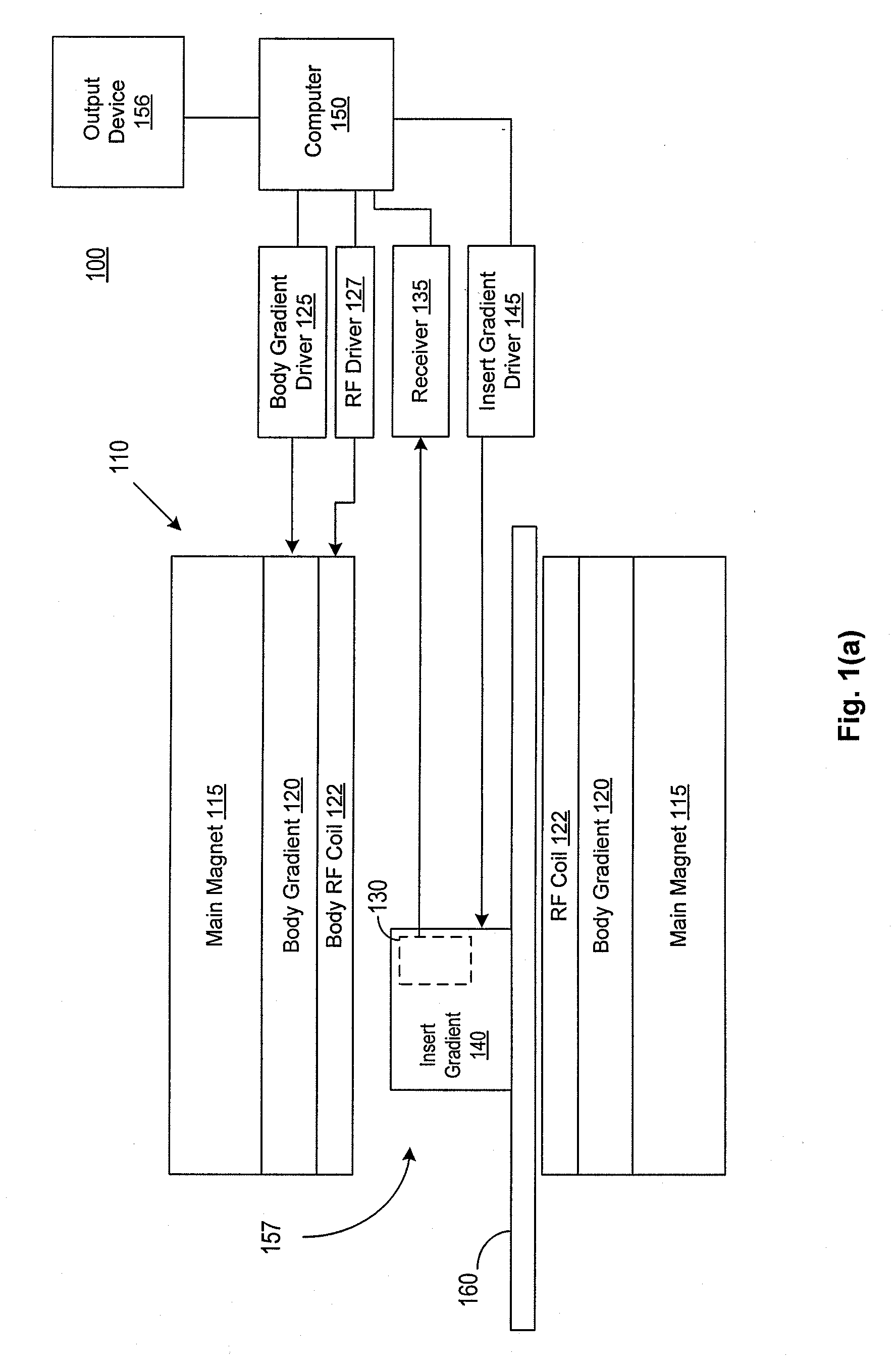
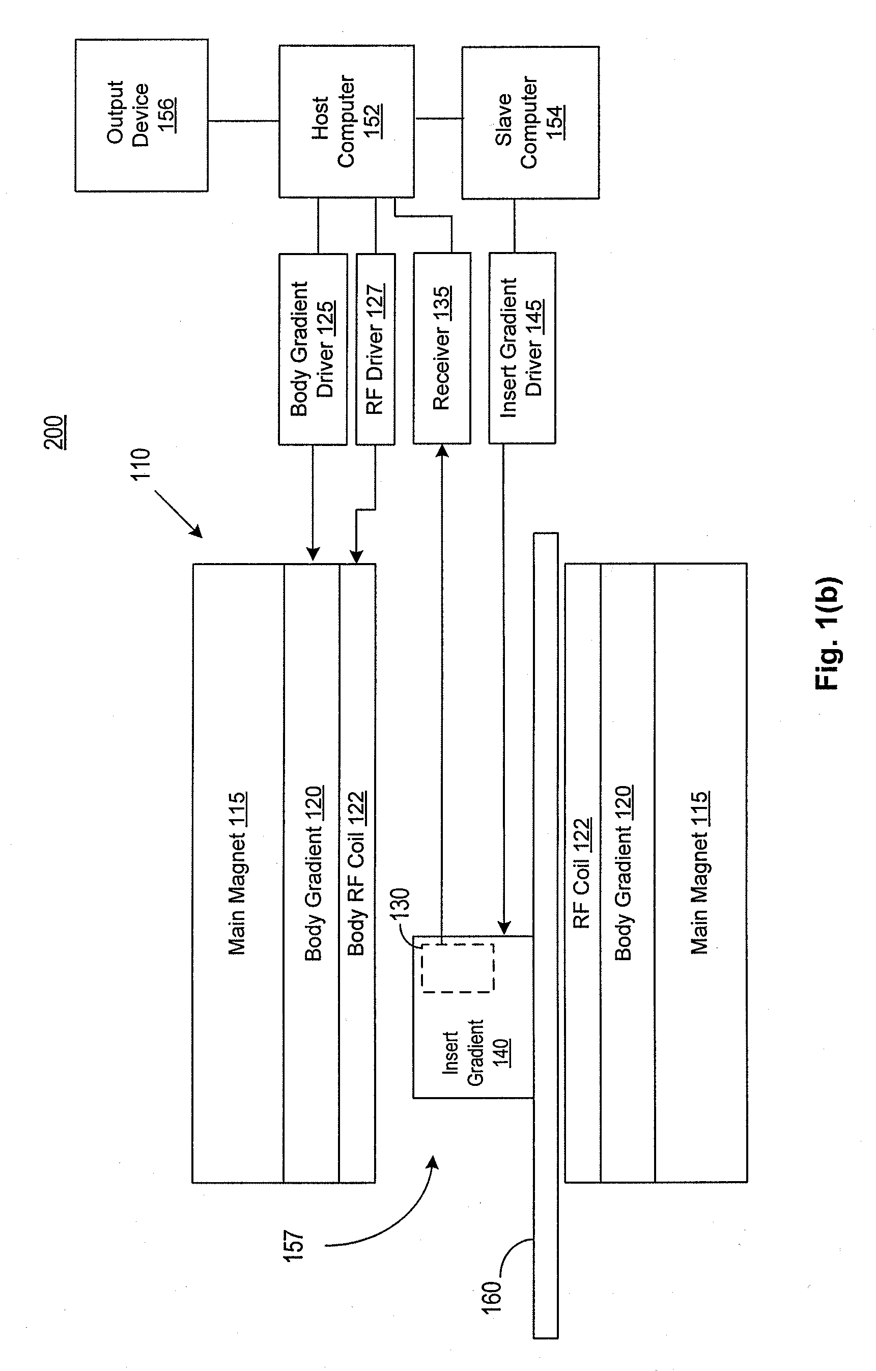
[0044]Insertable, reduced-volume gradient coils can provide substantial improvement in gradient speed and amplitude. Because conventional MRI systems have only one set of gradient amplifiers, connecting insert gradient coils requires disconnection of the body gradient coils. Thus, to use insert gradient coils for one pulse sequence on a patient usually requires that the insert gradient coils be used for all pulse sequences of the exam. Further, when the body gradient coils are disconnected, the linear first order gradient shimming that is normally performed with static currents applied to the three axes of the body gradients must be performed using the insert gradients which are typically less homogeneous than the body gradients. It is possible that only part of a single pulse sequence may require high gradient performance and that part may allow reduced homogeneity or reduced volume or both. As a simple example, slice selection that is performed using the insert gradients will be l...


PUM


Abstract

A composite gradient system is described, including a body gradient system and an insert gradient system, in which the body gradient system and the insert gradient system can be driven independently and simultaneously. The composite gradient system can provide an operator with the flexibility of imaging a subject using the body gradient system alone, the insert gradient system alone, or both gradient systems simultaneously, and therefore enjoy the advantages of each gradient system. In some embodiments, the body gradient system and the insert gradient system may be driven concurrently during an imaging sequence to produce composite magnetic field gradients having high amplitude and/or fast slew rate, resulting in high image resolution and/or fast image acquisition. In some embodiments, a subject may be imaged using the body gradient system alone while leaving the insert gradient system in place.

Description

RELATED APPLICATION[0001]The present application claims the benefit of priority under 35 U.S.C. §119 from U.S. Provisional Patent Application Ser. No. 61 / 05,766, entitled “DYNAMIC MULTI-GRADIENT SYSTEMS FOR ADVANCED MRI,” filed on Oct. 15, 2008, which is hereby incorporated by reference in its entirety for all purposes.STATEMENT REGARDING FEDERALLY SPONSORED RESEARCH OR DEVELOPMENT[0002]This invention was made with government support under Grant #EB004803 awarded by the National Institutes of Health. The government has certain rights in the invention.FIELD OF THE INVENTIONS[0003]The present disclosure relates to magnetic resonance imaging (MRI).BACKGROUND OF THE INVENTIONS[0004]In conventional gradient systems, gradient amplitude and speed are limitations in a number of important applications. Examples of MRI techniques where image quality is limited by gradient amplitudes and rise time limits include echoplanar (EPI), turbo spin echo (TSE), steady state free precession (SSFP), and ...

Claims


Application Information

Patent Timeline
Patent Type & Authority Applications(United States)
IPC IPC(8): G01R33/48
CPCG01R33/288G01R33/4835G01R33/385
Inventor PARKER, DENNIS LEEHADLEY, JOHN ROCKGOODRICH, KENNETH CRAIG
Owner UNIV OF UTAH RES FOUND
Why Eureka
Try Eureka