Isolated dc-dc converter

a dc-dc converter and isolation technology, applied in the direction of dc-dc conversion, power conversion systems, instruments, etc., can solve the problems of deterioration with time, digital controllers cannot communicate with load (electronic devices), and the above-described advantages cannot be obtained, so as to increase the size of the converter

Inactive Publication Date: 2010-04-29
MURATA MFG CO LTD
View PDF6 Cites 41 Cited by
  • Summary
  • Abstract
  • Description
  • Claims
  • Application Information

AI Technical Summary

Benefits of technology

[0014]Preferred embodiments of the present invention provide an isolated DC-DC converter capable of solving the ab...

Problems solved by technology

However, when the output voltage at the secondary side is transmitted to the primary side using a photocoupler, problems such as delay in response and deterioration with time may arise.
Moreover, when the digital controller is disposed at the primary side, the digital controller cannot communicate with a load (electronic device) to which the output voltage at the secondary side is applied.
However, when the digital controller is disposed at the primary side, the above-described advantages cannot be obtained.
However, a number of phot...

Method used


Image

  • Isolated dc-dc converter
  • Isolated dc-dc converter
  • Isolated dc-dc converter

Examples


Embodiment Construction

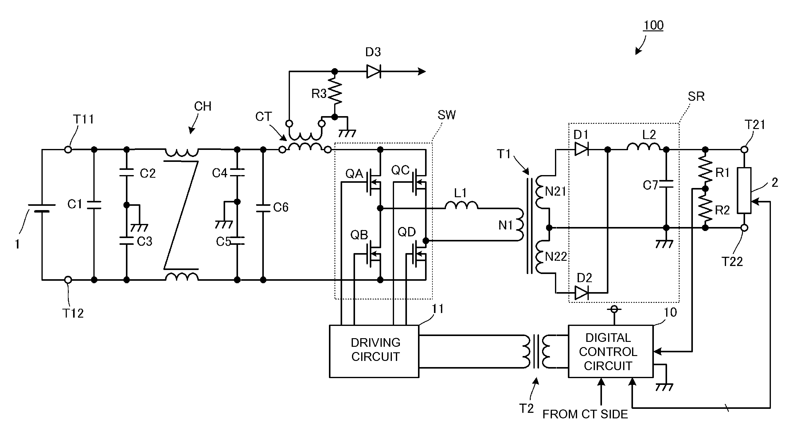
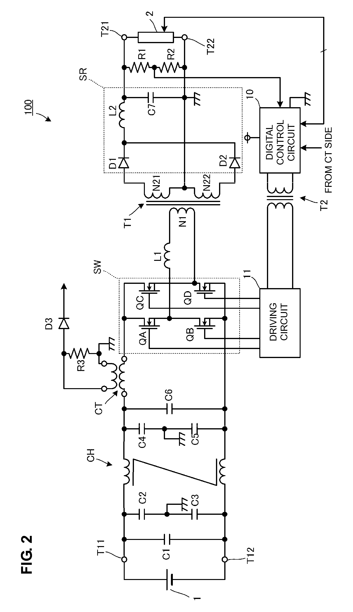
[0037]FIG. 2 is a circuit diagram of an isolated DC-DC converter 100 according to a preferred embodiment of the present invention. In FIG. 2, a transformer T1 includes a primary winding N1 and secondary windings N21 and N22. The primary winding N1 is connected to an inductor L1 and a switching circuit SW including four switching elements QA, QB, QC, and QD that define a bridge. A common mode choke coil CH, a filter circuit including by-pass capacitors C1 to C6, and a current transformer CT are disposed between an input power supply 1 and the switching circuit. A resistor R3 and a rectifying diode D3 are connected to a secondary side of the current transformer CT so that current flowing in a primary side of the current transformer is extracted as voltage signals. A circuit including this current transformer CT corresponds to a current detector according to a preferred embodiment of the present invention.

[0038]The four switching elements QA to QD of the switching circuit SW are connec...


PUM


Abstract

A switching circuit arranged to switch the input of an input power supply is connected to a primary winding of a transformer at a primary side of the transformer. A digital control circuit including a switching controller arranged to output control pulses to the switching circuit and a rectifying/smoothing circuit connected to secondary windings of the transformer are disposed at a secondary side of the transformer. The digital control circuit outputs the control pulses via a pulse transformer, calculates the input power-supply voltage on the basis of the on-duty cycle of the control pulses, the output voltage, and the ratio of the number of turns of the primary winding to the number of turns of the secondary windings of the transformer, and performs converter control in accordance with the calculated input power-supply voltage.

Description

BACKGROUND OF THE INVENTION[0001]1. Field of the Invention[0002]The present invention relates to isolated DC-DC converters that digitally control switching circuits.[0003]2. Description of the Related Art[0004]Japanese Unexamined Patent Application Publication No. 2000-116027 describes a known isolated DC-DC converter for digital control including a control circuit configured using a microcomputer or a DSP (digital signal processor) to maintain the output voltage at a secondary side at a constant value.[0005]Since the microcomputer or the DSP can communicate signals and data with an external circuit, the performance of the converter can be improved when the microcomputer or the DSP is used for switching control.[0006]Herein, FIG. 1 illustrates a basic structure of the isolated DC-DC converter described in Japanese Unexamined Patent Application Publication No. 2000-116027.[0007]In FIG. 1, a switching element 211 and a resistor 257 for current detection are connected in series to a pr...

Claims


Application Information

Patent Timeline
IPC IPC(8): H02M3/335
CPCH02M2001/0019H02M3/3376H02M1/0019
Inventor NISHIYAMA, TAKAYOSHIUEKI, KOICHI
Owner MURATA MFG CO LTD
Why Eureka
Try Eureka