Magnetic memory cell

a technology of magnetic memory cell and logic circuit, which is applied in the direction of information storage, static storage, digital storage, etc., can solve the problems of reducing the degree of integration attributable to the circuit added to the mtj device, increasing the number of processes, and increasing so as to reduce the number of manufacturing processes for memory cells and reduce the manufacturing cost of memory cells. , the effect of reducing the number of metal input layers

Active Publication Date: 2010-04-29
EWHA UNIV IND COLLABORATION FOUND
View PDF13 Cites 20 Cited by
  • Summary
  • Abstract
  • Description
  • Claims
  • Application Information

AI Technical Summary

Benefits of technology

[0015]The present invention is advantageous in that the magnetization direction of the free layer of an MTJ device is changed using spin torque transfer, thus enabling additional metal input layers to be eliminated.
[0016]Further, the present invention is advantageous in that, as additional metal input layers are eliminated, the number of processes for manufacturing memory cells can be reduced, and the manufacturing costs of memory cells can be decreased.
[0017]Further,

Problems solved by technology

However, there are problems in that, since three metal input layers are provided to change the magnetization direction of the free magnetic layer of the MTJ device, the number of processes increases and the manufacturing costs thereof increase, and in that, since current driving circuits for respective metal input layers are added, the

Method used


Image

  • Magnetic memory cell
  • Magnetic memory cell
  • Magnetic memory cell

Examples


Embodiment Construction

[0050]Hereinafter, embodiments of the present invention will be described in detail with reference to the attached drawings.

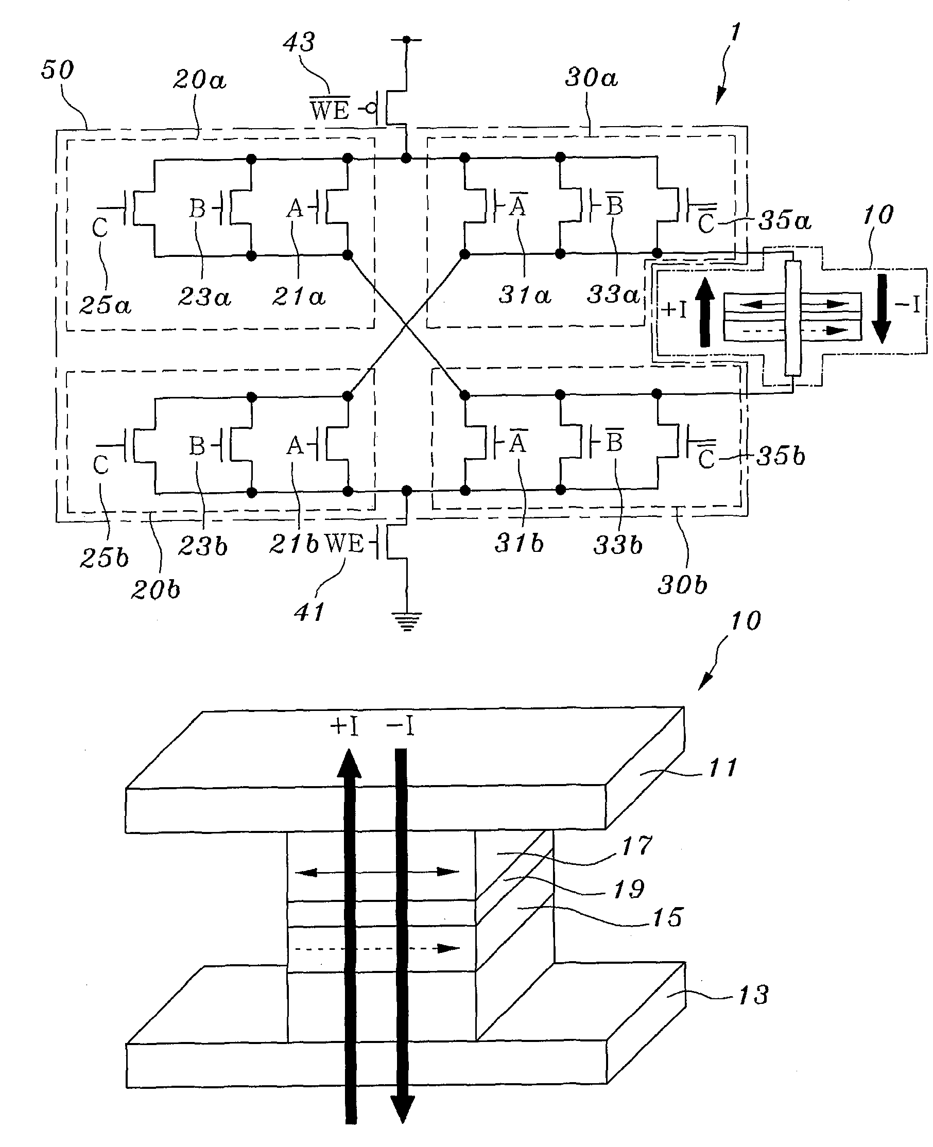
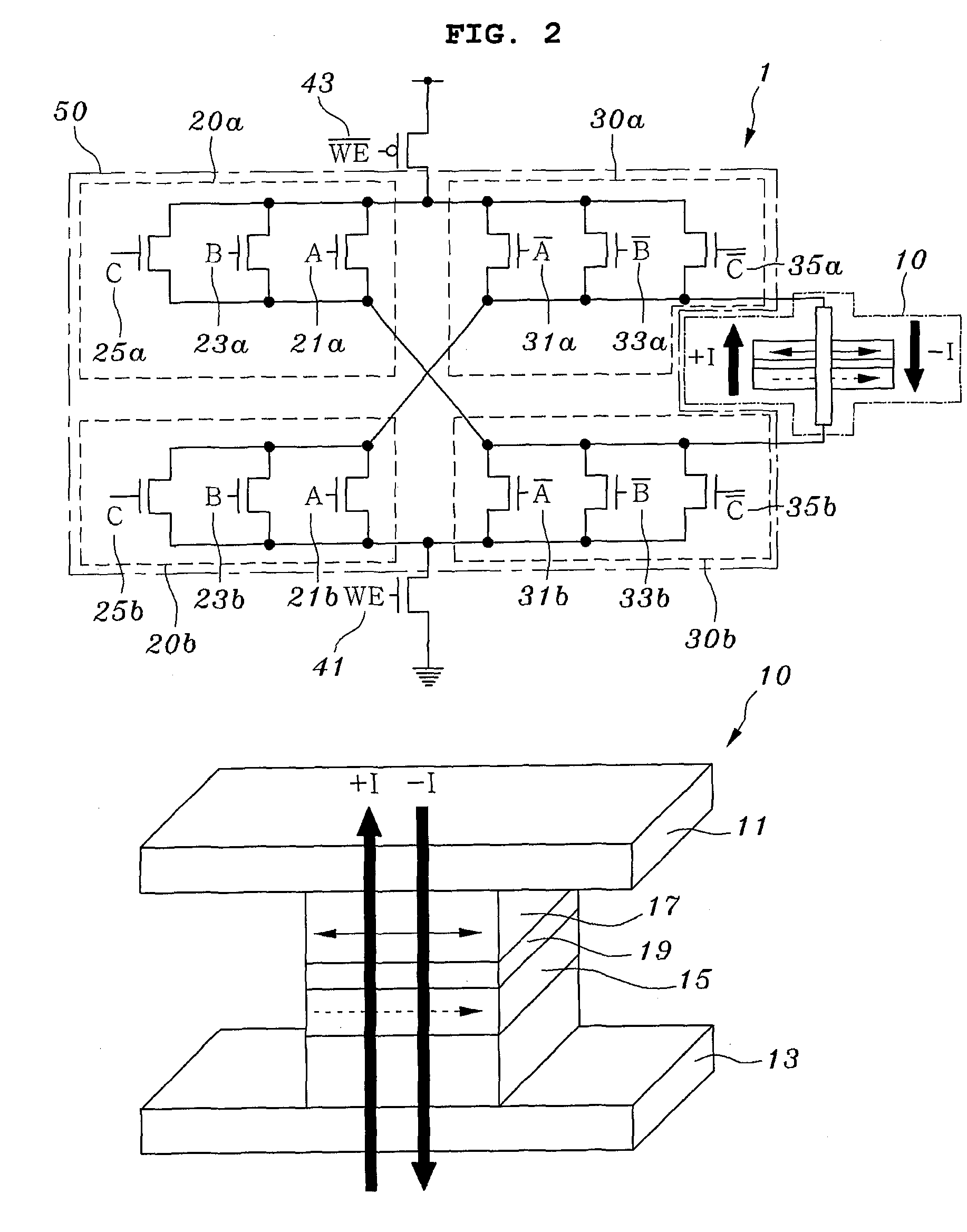
[0051]FIG. 2 illustrates a circuit diagram and a partially enlarged diagram schematically showing a magnetic memory cell according to the present invention. As shown in the drawings, a magnetic memory cell 1 according to the present invention includes a Magnetic Tunnel Junction (MTJ) device 10 and a current control circuit 50.

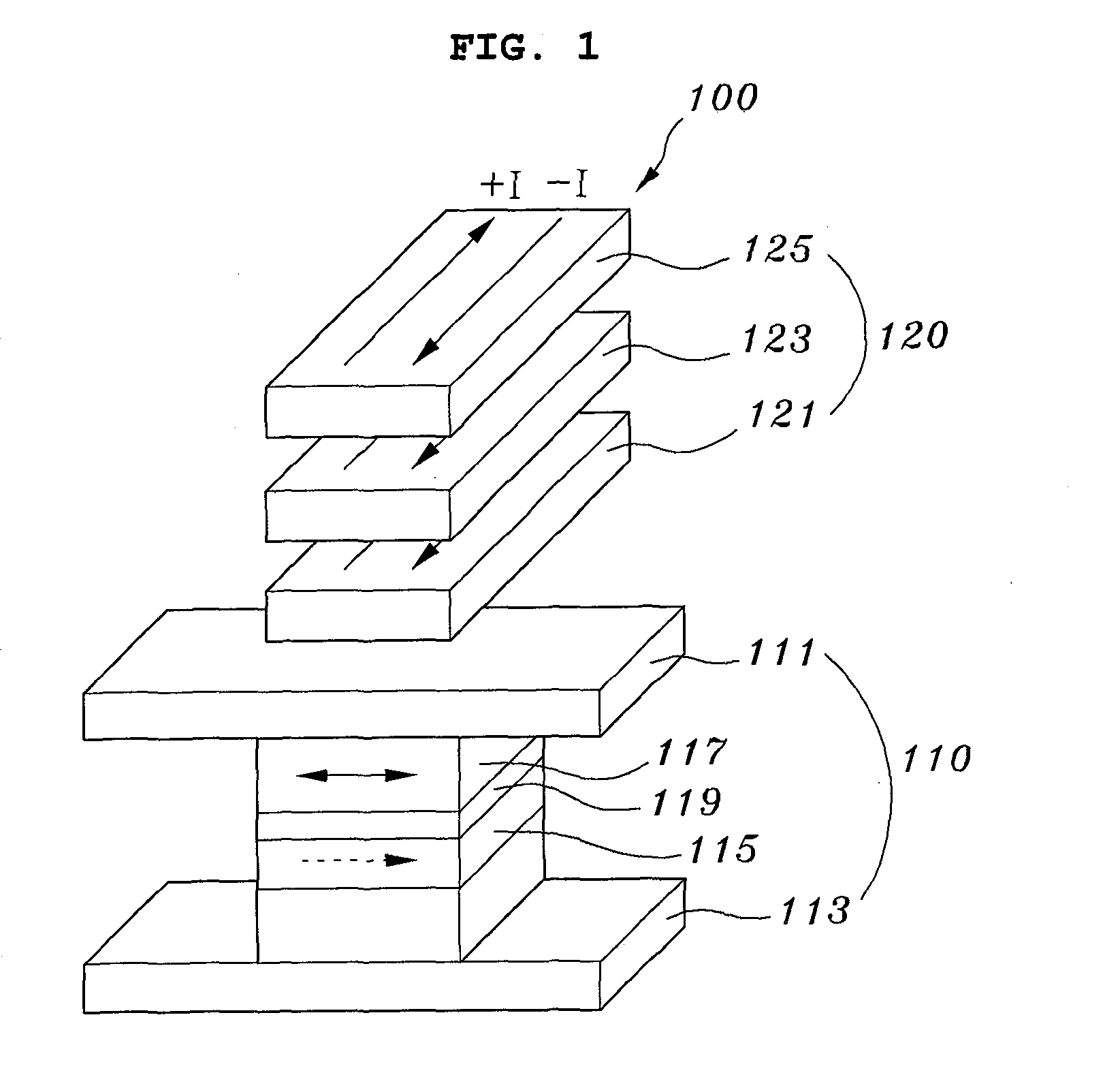
[0052]In this case, the MTJ device 10 includes a fixed layer 15 and a free layer 17, which are magnetic layers deposited between a top electrode 11 and a bottom electrode 13, and an insulating layer 19 deposited between the fixed layer 15 and the free layer 17 to insulate them from each other.

[0053]Further, the magnetization direction of the fixed layer 15 is fixed to the right direction, and is continuously maintained in the right direction regardless of the direction of current applied by the current control circuit 50.

[0054]Here, the MT...


PUM


Abstract

The present invention relates to a magnetic memory cell, which controls the magnetization direction of the free magnetic layer of a Magnetic Tunnel Junction (MTJ) device using a spin torque transfer, and enables the implementation of a magnetic logic circuit, in which memory and logic circuit functions are integrated. The magnetic memory cell includes an MTJ device (10) including a top electrode (11) and a bottom electrode (13), which are provided to allow current to flow therethrough, and a fixed layer (15) and a free layer (17), which are magnetic layers respectively deposited on a top and a bottom of an insulating layer (19), required to insulate the top and bottom electrodes from each other. A current control circuit (50) controls a flow of current flowing between the top and bottom electrodes, and changes a magnetization direction of the free layer according to an input logic level.

Description

TECHNICAL FIELD[0001]The present invention relates, in general, to the configuration of a logic circuit using a magnetic memory cell, and, more particularly, to a magnetic memory cell, which controls the magnetization direction of the free magnetic layer of a Magnetic Tunnel Junction (MTJ) device using a spin torque transfer, and enables the implementation of a magnetic logic circuit, in which memory and logic circuit functions are integrated, using the magnetization direction.BACKGROUND ART[0002]Generally, a logic circuit using a magnetic tunnel junction is operated such that, when the same current flows through an input terminal, the magnetization direction of a free magnetic layer is changed, whereas when the directions of currents are different from each other, the magnetization direction of the free magnetic layer is not changed. Accordingly, the magnetic spin of the free magnetic layers within intersecting cells can be arranged in desired directions due to a combined magnetic ...

Claims


Application Information

Patent Timeline
IPC IPC(8): G11C11/15G11C7/00
CPCG11C11/16G11C11/1675G11C11/1697G11C11/15G11C11/161G11C11/165H10B61/00H10N50/10
Inventor SHIN, HYUNGSOON
Owner EWHA UNIV IND COLLABORATION FOUND
Why Eureka
Try Eureka