
Machine-readable medium for storing a stream data processing program and computer system

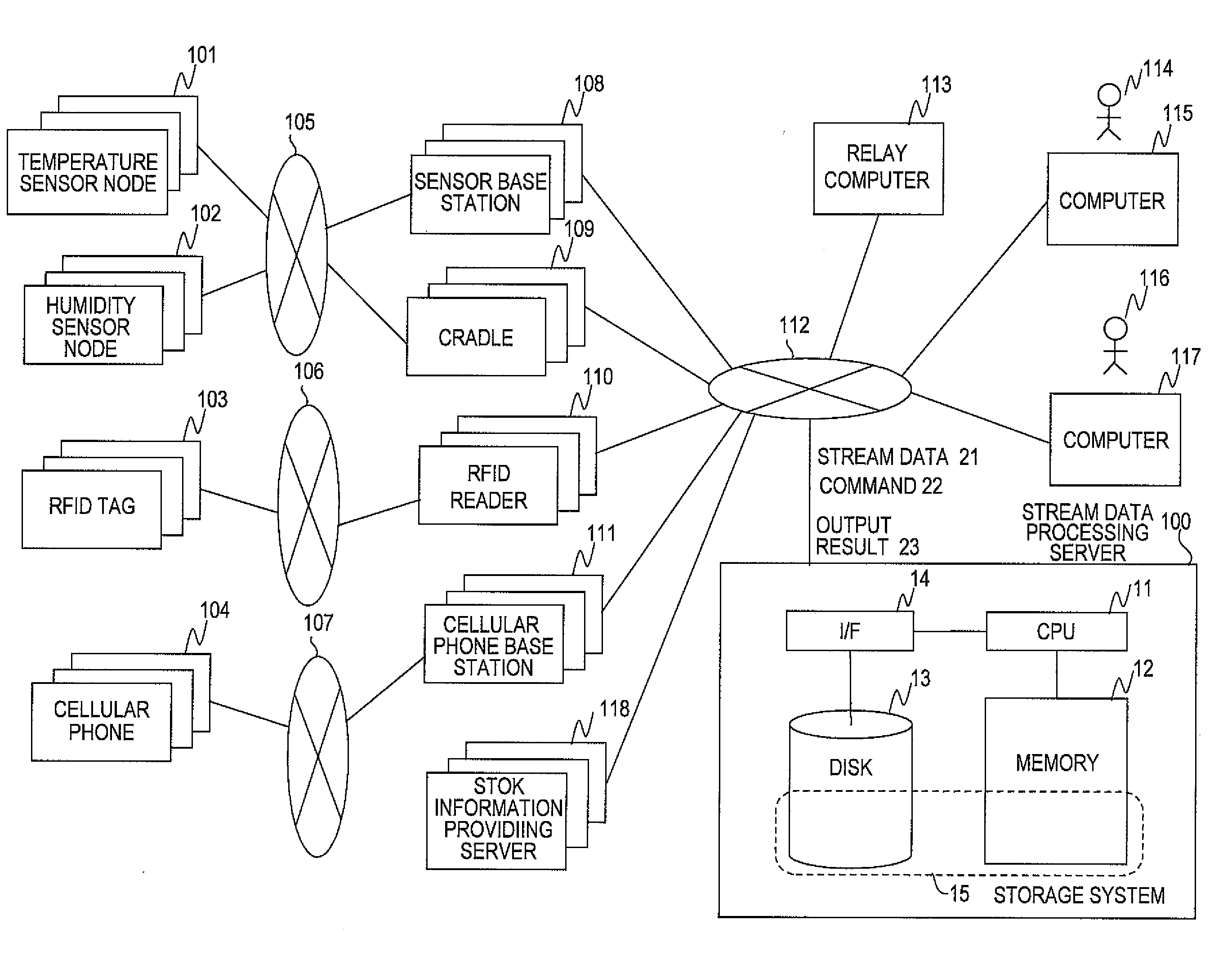
a computer system and data processing technology, applied in the field of stream data processing system, can solve the problems of system failure to realize business opportunities, increase in cpu load, and difficulty in applying the mechanism to real-time data processing, and achieve the effect of reducing the amount of time control information and small latency

Inactive Publication Date: 2010-04-29
HITACHI LTD
View PDF3 Cites 40 Cited by
  • Summary
  • Abstract
  • Description
  • Claims
  • Application Information

AI Technical Summary

Benefits of technology

[0015]In US 2008 / 0072221, HBTs are generated regularly, leaving unsolved the problem of a rise in CPU load, lowering in throughput and, ultimately, an overhead as a result of increasing the HBT generation rate in an attempt to reduce the latency.
[0021]By applying this invention, stream data processing that is small in latency is accomplished while the amount of the time control information is reduced.

Problems solved by technology

Storing stock data in a storage system temporarily and then conducting a search concerning the stored data as in conventional DBMSs takes too long for the speed of change in stock price, possibly causing the system to miss a business chance.
U.S. Pat. No. 5,495,600, for example, discloses a mechanism that executes a stored query cyclically, but it is difficult to apply the mechanism to processing of real-time data such as stock prices, in which executing a query the instant data is input is important.
Reducing the latency requires an increased HBT generation rate, which causes a rise in CPU load, lowering in throughput and, ultimately, an overhead.
Further, in the case where a plurality of computers are involved and time information in a first computer is used by a second computer for stream data processing, the need to transmit the time information in the first computer to the second computer creates a problem similar to the one described above.
There may arise another problem that a long execution tree with may queries registered needs to be tracked back many times.

Method used


Image

  • Machine-readable medium for storing a stream data processing program and computer system
  • Machine-readable medium for storing a stream data processing program and computer system
  • Machine-readable medium for storing a stream data processing program and computer system

Examples


second embodiment

[0188]A second embodiment of this invention is described below.

[0189]The first embodiment has described that a wait in the query execution module 226 may be solved in the stream data processing sever 100 by making the HBT generation module 224 generate an HBT for advancing time during a period in which no data is generated at the time when the HBT is needed.

[0190]The second embodiment discusses a case in which a plurality of computers are involved and time information in a first computer is used to execute stream data processing in a second computer. In this case, too, a problem similar to the wait problem of the query execution module 226 described above arises due to the need to transmit the time information in the first computer to the second computer.

[0191]The second embodiment is characterized in that, in a setting in which contains a plurality of computers are involved and time information in a first computer is used to execute stream data processing in a second computer, the ...


PUM


Abstract

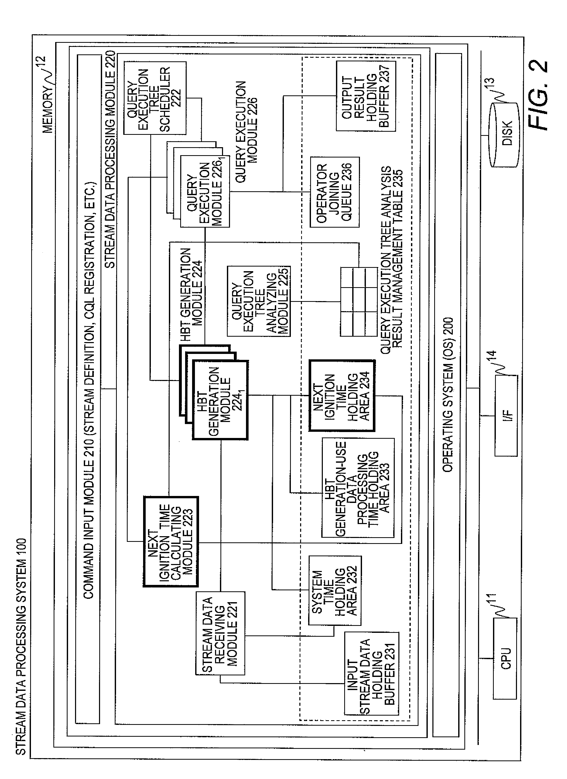
In a stream data processing method in which part of stream data is defined as a processing target and the time control information which indicates the advance of the time is inserted into the stream data, time information of the received stream data is stored in a next ignition time holding area as an ignition time. A processing module for generating the time control information at a time different from the time of reception of the stream data is extracted out of a query that indicates how the stream data is to be processed. Based on the extracted processing module and the time information indicating the time of the reception of the stream data, the ignition time is calculated and stored in the next ignition time holding area. The time generation module inserts the time control information at the ignition time held in the next ignition time holding area.

Description

CLAIM OF PRIORITY[0001]The present application claims priority from Japanese patent application JP2008-276685 filed on Oct. 28, 2008, the content of which is hereby incorporated by reference into this application.BACKGROUND OF THE INVENTION[0002]This invention relates to a method of, in a stream data processing system, generating time control information inside the system and between the systems.[0003]There has been an increasing demand for a data processing system which carries out real-time processing for data continuously arriving at a database management system (hereafter, referred to as “DBMS”), which carries out processes for data stored in the storage system.[0004]Data which continuously arrives is defined as stream data, and there has been proposed a stream data processing system as a data processing system suitable for the real-time processing for the stream data. For example, R. Motwani, J. Widom, A. Arasu, B. Babcock, S. Babu, M. Datar, G. Manku, C. Olston, J. Rosenstein,...

Claims


Application Information

Patent Timeline
Patent Type & Authority Applications(United States)
IPC IPC(8): G06F15/16
CPCG06Q10/06G06Q40/04G06Q10/109
Inventor KASHIYAMA, TOSHIHIKONISHIZAWA, ITARUIMAKI, TSUNEYUKI
Owner HITACHI LTD
Learn More