Ultra Thin Glass Drawing and Blowing

Inactive Publication Date: 2010-05-06
CORNING INC
View PDF27 Cites 23 Cited by
  • Summary
  • Abstract
  • Description
  • Claims
  • Application Information

AI Technical Summary

Benefits of technology

[0018]Among other advantages, the heating and blowing apparatus is compact and yet delivers large thin sheet width, in contrast to a larger, conventional drawing process. Moreover, whereas the conventional drawing process may either dramatically reduce the sheet width or just maintain it with glass losses on each side, there is little to no width or diameter reduction under drawing according to the present invention.
[0019]Also, use of an updraw allows a floor level set up and upward glass envelope evacuation. Thanks to

Problems solved by technology

Producing flat product glass for displays, such as OLEDS and liquid crystal displays (LCDs), involves many challenges.
Glass, however, is not generally a very flexible material, except possibly when the glass is ultra thin, so using glass in the creation of flexible OLED displays would require creation of glass thin enough to flex without breaking.
However, the traditional OLED displays, and in particular the electrodes and organic layers located therein, are susceptible to degradation resulting from interaction with oxygen and moisture

Method used


Image

  • Ultra Thin Glass Drawing and Blowing
  • Ultra Thin Glass Drawing and Blowing
  • Ultra Thin Glass Drawing and Blowing

Examples


Embodiment Construction

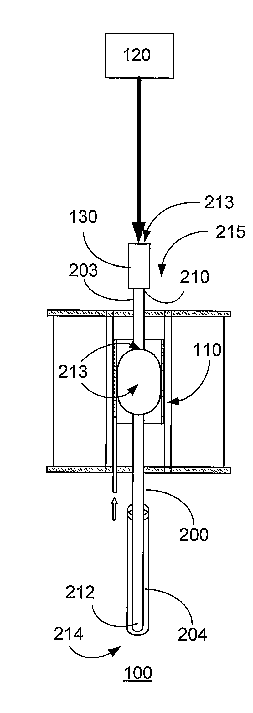
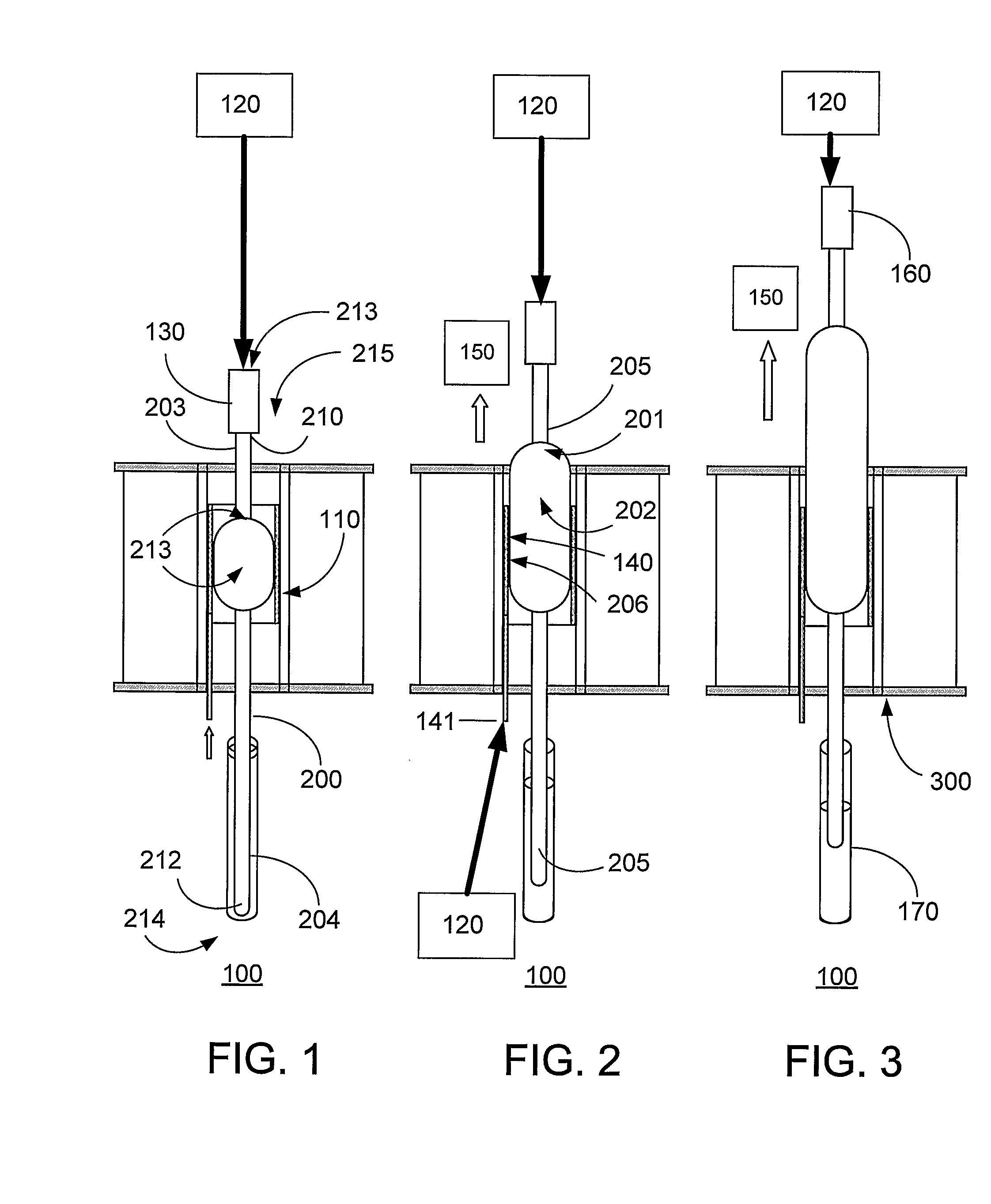
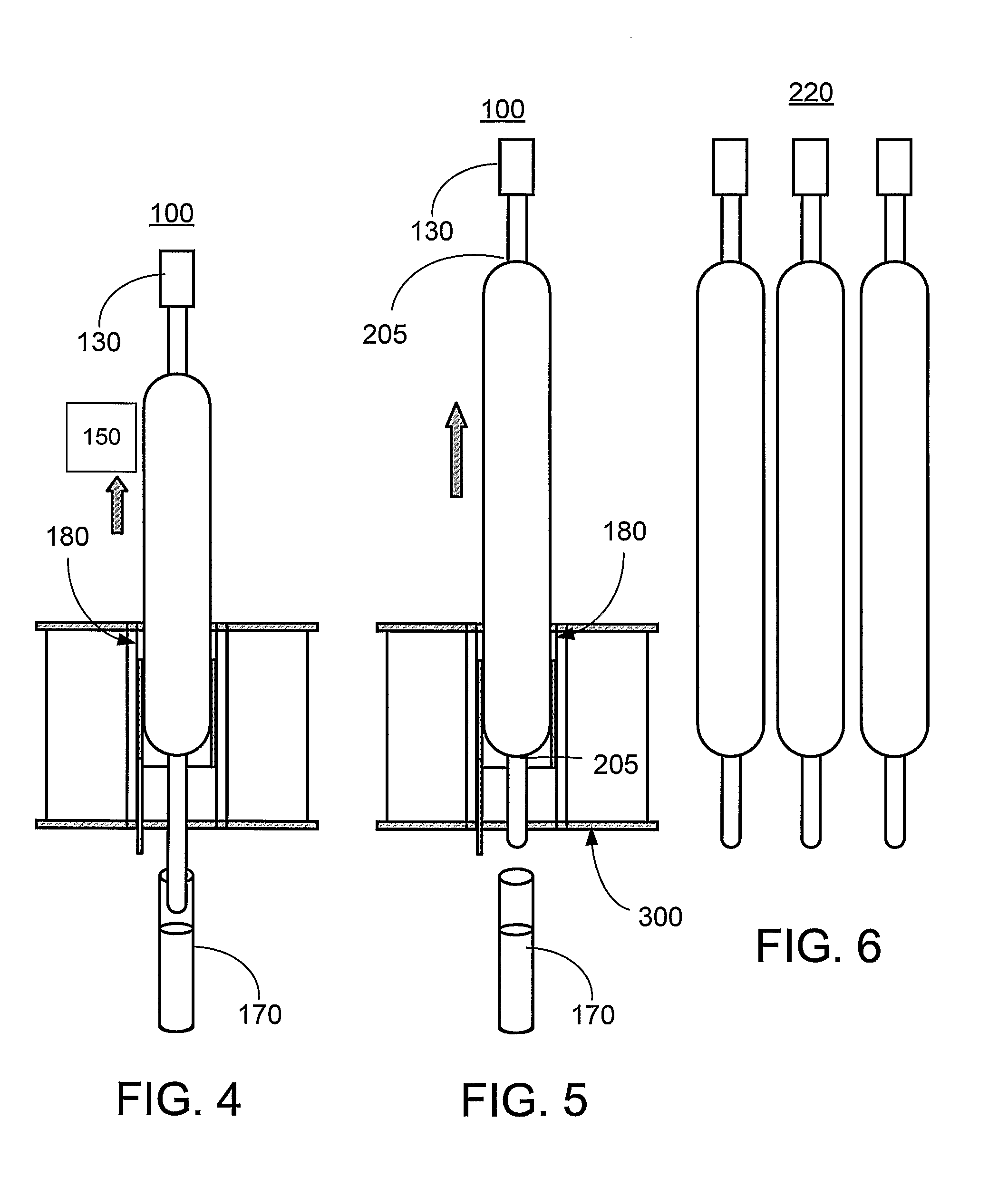
[0031]The present invention relates to methods, systems, apparatus and products related to drawing and blowing of ultra thin glass substrates. In particular, the present invention relates to a process for manufacturing ultra thin glass, for example, for use in flexible display applications.

[0032]Given that displays historically have been rigid, glass substrates commonly have been made using a process known as the fusion process (e.g., downdraw process) to form high quality thin glass sheets that can be used in a variety of devices like flat panel displays. The fusion process is the preferred technique for producing glass sheets used in flat panel displays because the glass sheets produced by this process have surfaces with superior flatness and smoothness when compared to glass sheets produced by other methods. The general fusion process is described in numerous publications, such as U.S. Pat. Nos. 3,338,696 and 3,682,609, and is well-known in the art.

[0033]By way of example, the pr...


PUM

PropertyMeasurementUnit
Forceaaaaaaaaaa
Diameteraaaaaaaaaa
Lengthaaaaaaaaaa

Abstract

Systems, methods, apparatus and products relate to drawing and blowing of ultra thin glass substrates, such as flexible display glass sheets, for example, organic light emitting diode (OLED) displays, liquid crystal displays (LCDs), and/or other flexible substrate applications, such as lighting, and/or other technologies, such as electro-wetting (EW), electro-phoretic display applications, etc. A localized heat source centripetally heats a vertical glass pre-form, while a pressurized air source blows the heated glass to expansion. An air bearing may centripetally blow air against the expanding pre-form to limit expansion and prevent contact of the pre-form with the localized heat source. Meanwhile, the pre-form is pulled vertically to draw the heated glass. The pre-form may float in a floatation mechanism to compensate for gravity when the pre-form is pulled upward. The blown and drawn pre-form may be cooled, coated with a polymer layer, and cut into a ribbon by in-line devices as it exits the air bearing. For example, a laser may helicoidally cut a polymer-coated blown and drawn pre-form into a ribbon, which may be rolled for collection.

Description

BACKGROUND[0001]1. Field of Invention[0002]The present invention relates to methods, systems, apparatus and products relating to drawing and blowing of ultra thin glass substrates, such as flexible display glass sheets for use in organic light emitting diode (OLED) displays.[0003]2. Description of Related Art[0004]Producing flat product glass for displays, such as OLEDS and liquid crystal displays (LCDs), involves many challenges. While LCDs typically require rigid display glass having minimal product distortion, such as arises due to internal stresses in large product glass plates, OLED technology is moving in the direction of providing flexible displays. Therefore, flexible polymer substrates are under investigation for use in OLED displays. Glass, however, is not generally a very flexible material, except possibly when the glass is ultra thin, so using glass in the creation of flexible OLED displays would require creation of glass thin enough to flex without breaking.[0005]Organi...

Claims


Application Information

Patent Timeline
IPC IPC(8): C03C17/00C03B9/02C03B9/12C03B9/46
CPCC03B23/045C03B23/047C03B23/07C03B33/06C03B33/0955C03B9/03C03B9/30C03B9/32C03B11/10
Inventor DANNOUX, THIERRY LUC ALAINVANOTTI, CLAUDE JACQUES JULIEN
Owner CORNING INC
Why Eureka
Try Eureka