
Balance step-height selective bi-channel structure on hkmg devices

a bi-channel structure and step-height technology, applied in the direction of semiconductor devices, electrical equipment, transistors, etc., can solve the problems of high threshold voltage and high k of metal gate stacks

Active Publication Date: 2010-05-06
TAIWAN SEMICON MFG CO LTD
View PDF3 Cites 51 Cited by
  • Summary
  • Abstract
  • Description
  • Claims
  • Application Information

AI Technical Summary

Benefits of technology

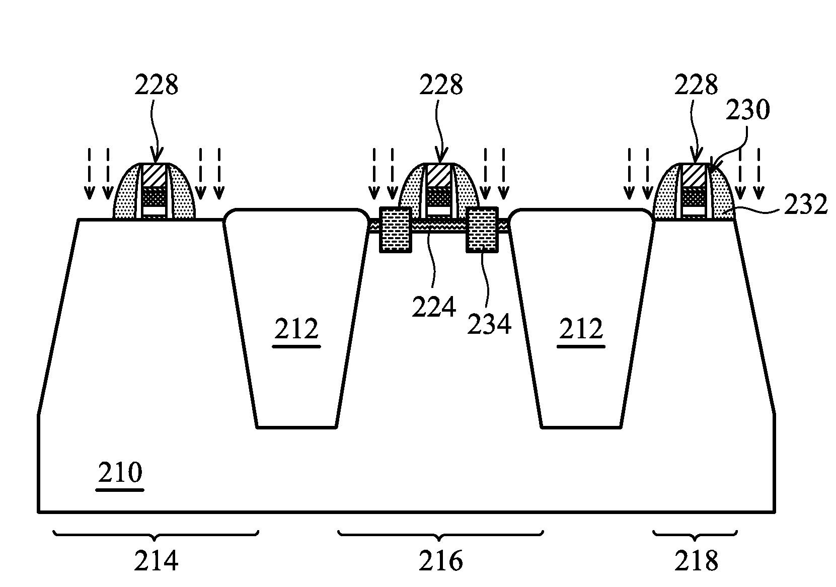
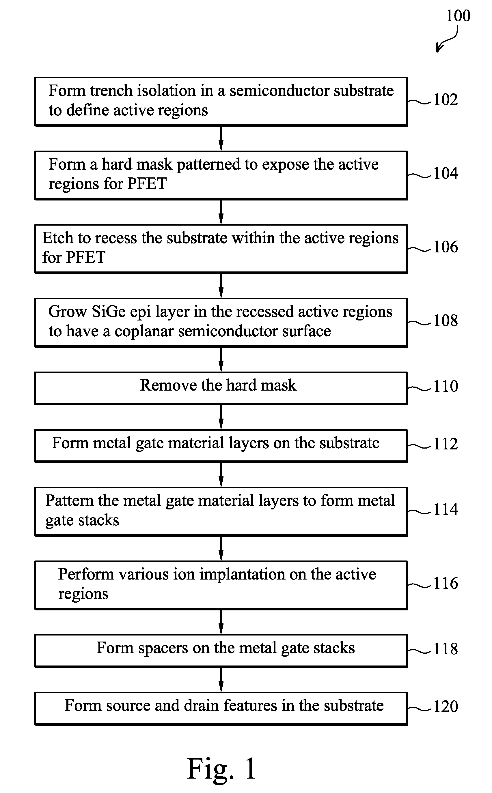
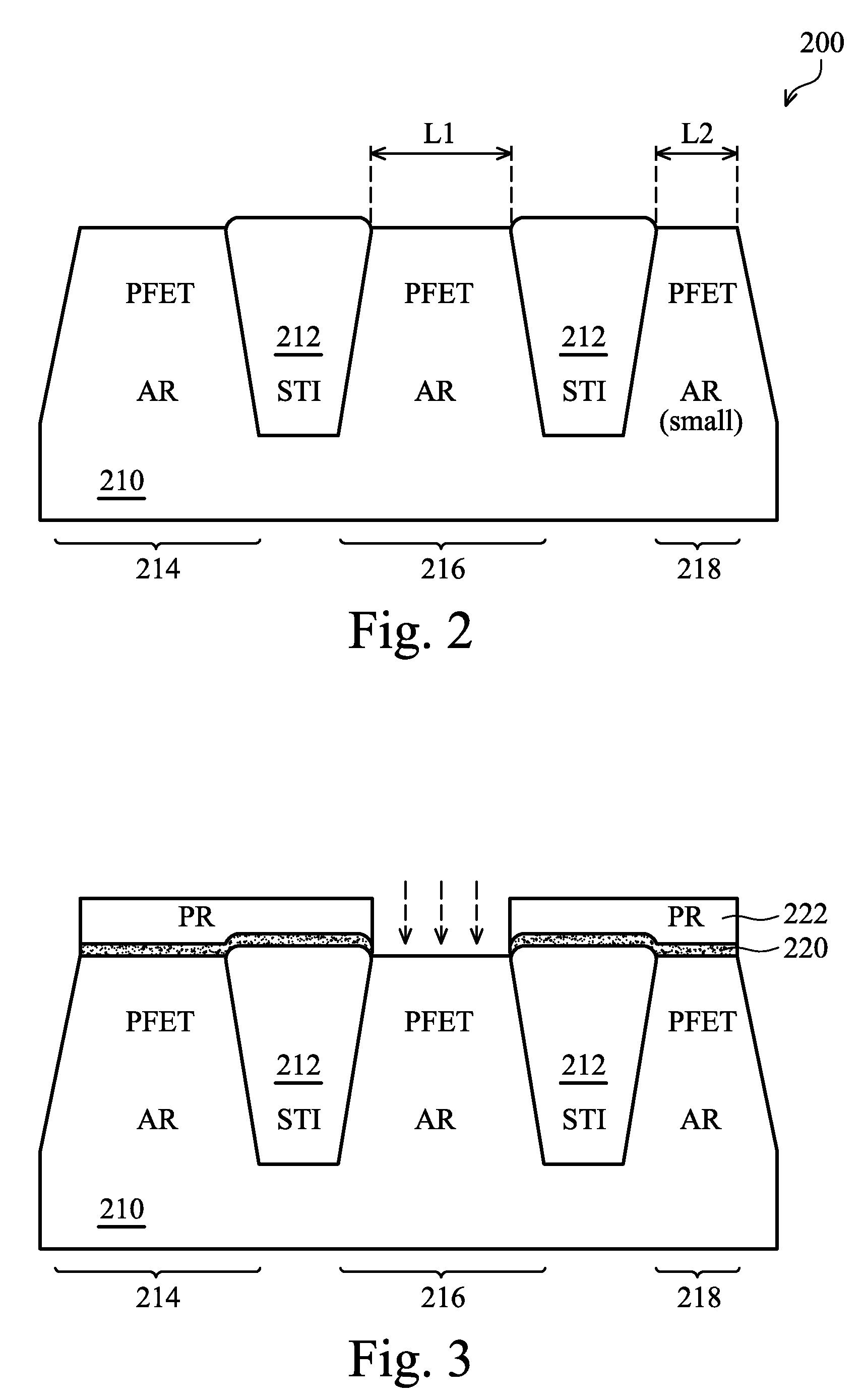
[0003]One of the broader forms of an embodiment of the present invention involves a method for making a semiconductor device having metal gate stacks. The method includes forming shallow trench isolation (STI) features in a silicon substrate, defining a first active region configured for a p-type field effect transistor (PFET) and a second active region configured for an n-type field effect transistor (NFET); forming, on the silicon substrate, a hard mask having an opening to expose the silicon substrate within the first active region; etching the silicon substrate through the opening of the hard mask to form a recess in the silicon substrate within the first active region; growing a silicon germanium (SiGe) layer in the recess such that a top surface of the SiGe layer within the first active region and a top surface of the silicon substrate within the second active region are substantially coplanar; forming metal gate material layers on the silicon substrate and the SiGe layer; patterning the metal gate material layers to form a metal gate stack on the SiGe layer within the first active region; and forming an eSiGe source / drain (S / D) stressor distributed in both the SiGe layer and the silicon substrate within the first active region.

Problems solved by technology

However, the high k and metal gate stack suffers from the high threshold voltage for a p-type FET.

Method used


Image

  • Balance step-height selective bi-channel structure on hkmg devices
  • Balance step-height selective bi-channel structure on hkmg devices
  • Balance step-height selective bi-channel structure on hkmg devices

Examples


Embodiment Construction

[0009]It is to be understood that the following disclosure provides many different embodiments, or examples, for implementing different features of various embodiments. Specific examples of components and arrangements are described below to simplify the present disclosure. These are, of course, merely examples and are not intended to be limiting. In addition, the present disclosure may repeat reference numerals and / or letters in the various examples. This repetition is for the purpose of simplicity and clarity and does not in itself dictate a relationship between the various embodiments and / or configurations discussed. Moreover, the formation of a first feature over or on a second feature in the description that follows may include embodiments in which the first and second features are formed in direct contact, and may also include embodiments in which additional features may be formed interposing the first and second features, such that the first and second features may not be in d...


PUM


Abstract

The present disclosure provides a method including forming STI features in a silicon substrate, defining a first and a second active regions for a PFET and an NFET, respectively; forming a hard mask having an opening to expose the silicon substrate within the first active region; etching the silicon substrate through the opening to form a recess within the first active region; growing a SiGe layer in the recess such that a top surface of the SiGe layer within the first active region and a top surface of the silicon substrate within the second active region are substantially coplanar; forming metal gate material layers; patterning the metal gate material layers to form a metal gate stack on the SiGe layer within the first active region; and forming an eSiGe S / D stressor distributed in both the SiGe layer and the silicon substrate within the first active region.

Description

PRIORITY DATA[0001]This application claims priority to Provisional Application Ser. No. 61 / 110,872 filed on Nov. 3, 2008, entitled “A Balance Step-Height Selective Bi-Channel Structure on HKMG Devices,” the entire disclosure of which is incorporated herein by reference.BACKGROUND[0002]When a semiconductor device such as a field-effect transistor (FET) is scaled down through various technology nodes, high k dielectric materials and metals are adopted to form a gate stack. However, the high k and metal gate stack suffers from the high threshold voltage for a p-type FET. Therefore, a semiconductor device and a method of making the same are needed to address the above issue.SUMMARY[0003]One of the broader forms of an embodiment of the present invention involves a method for making a semiconductor device having metal gate stacks. The method includes forming shallow trench isolation (STI) features in a silicon substrate, defining a first active region configured for a p-type field effect ...

Claims


Application Information

Patent Timeline
Patent Type & Authority Applications(United States)
IPC IPC(8): H01L27/092H01L21/20H01L21/8238
CPCH01L21/823807H01L29/1054H01L29/1083H01L29/165H01L29/66651H01L29/66636H01L29/7848H01L29/6656H01L29/66628
Inventor NG, JIN-AUNYANG, WEN-CHIHCHEN, CHIEN-LIANGFEI, CHUNG-HAUCHANG, MAXIYOUNG, BAO-RUCHUANG, HARRY
Owner TAIWAN SEMICON MFG CO LTD
Learn More