Mechanical maze puzzle

Inactive Publication Date: 2010-05-06
INGMAN SR ROBERT THOMAS MITCHELL
View PDF11 Cites 4 Cited by
  • Summary
  • Abstract
  • Description
  • Claims
  • Application Information

AI Technical Summary

Benefits of technology

[0014]The puzzle of the present invention may preferably be constructed of polyvinyl chloride (PVC) though the puzzle may conceivably be constructed from any of a number of other materials such as molded plastic or other polymer, metal, fiberglass, cardboard, wood, or even glass, for example. The poten

Problems solved by technology

For example, easier versions may allow a user to view the maze while manipulating the puzzle, intermediate versions may allow a user to view only part of the maze while working the puzzle, and more difficult v

Method used


Image

  • Mechanical maze puzzle
  • Mechanical maze puzzle
  • Mechanical maze puzzle

Examples


first embodiment

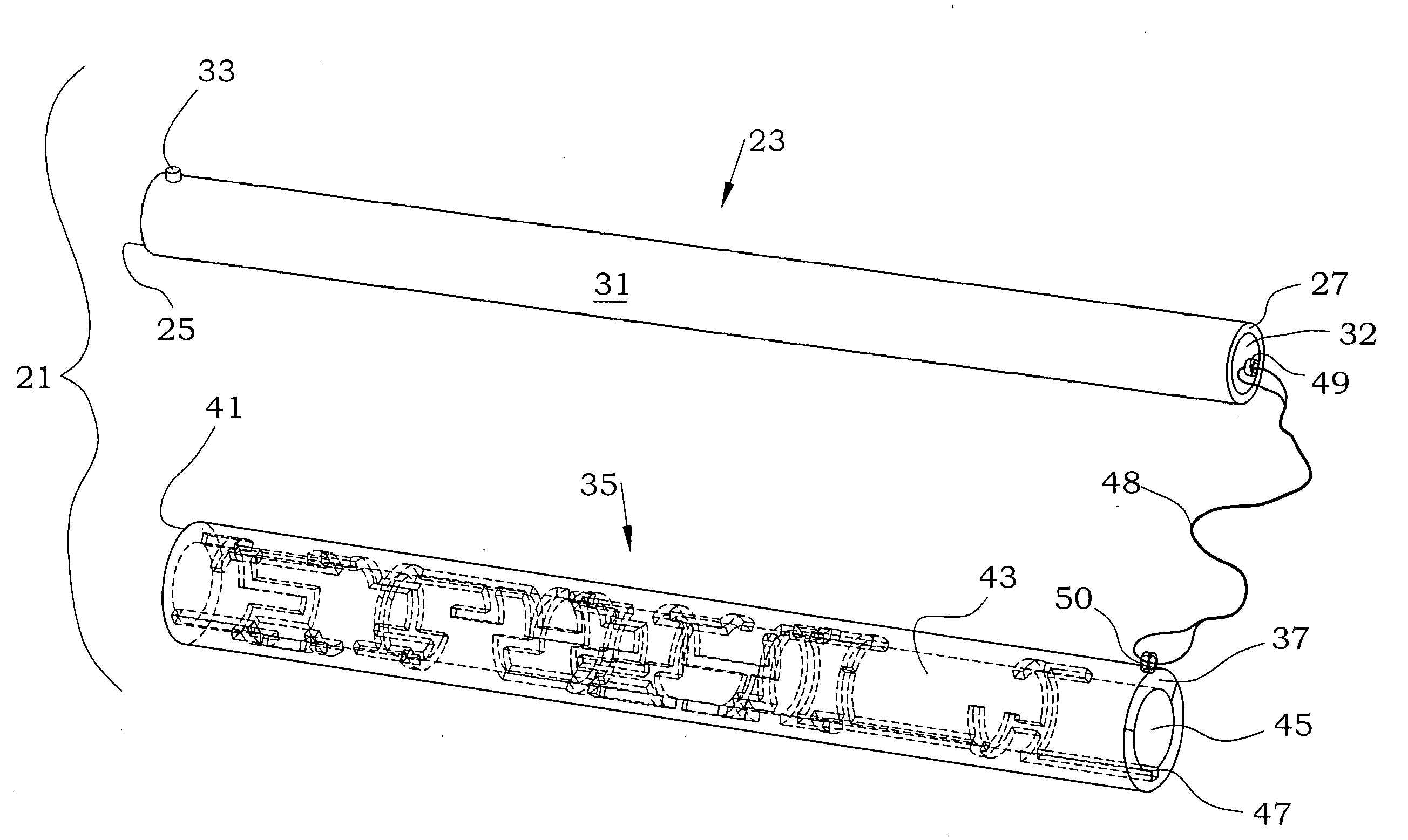
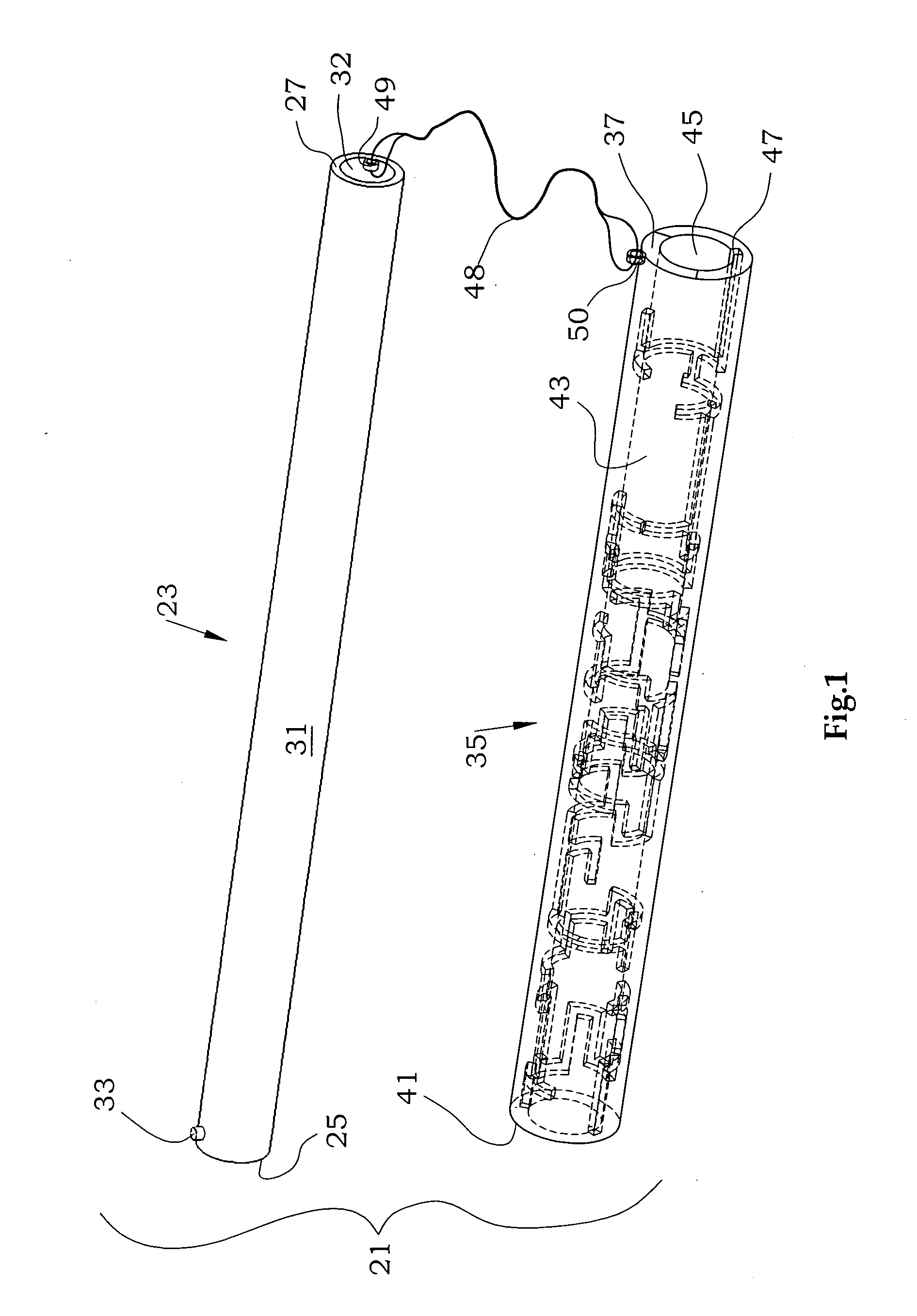
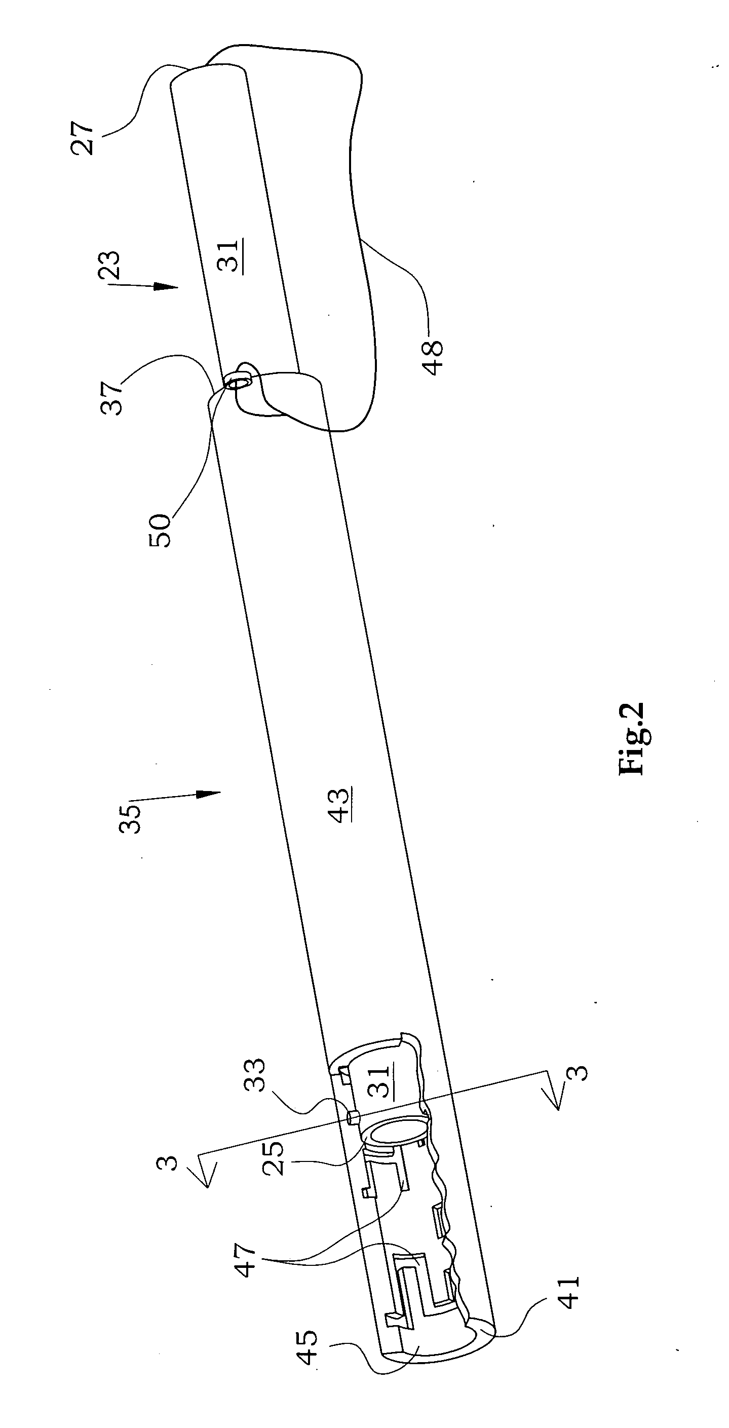
[0034]The description and operation of the invention will be best initiated with reference to FIG. 1, which is an exploded perspective view of the invention seen as puzzle 21 of the present invention.FIG. 1 illustrates a first cylinder 23 having a first end 25, a second end 27, an outer surface 31, an inner surface 32, and a pin 33 projecting from outer surface 31 near first end 25. Although pin 33 may be any size, it may preferably be about ⅛ of an inch in diameter and may project about ⅜ of an inch away from outer surface 31. Pin 33 may be formed integrally with the first cylinder 23, may be formed and inserted in a bore formed in first cylinder 23, or may be attached to first cylinder 23 in any other manner.

[0035]FIG. 1 illustrates a second cylinder 35 having a first end 37, a second end 41, an outer surface 43 and an inner surface 45 into which a groove 47 is cut to form a maze pattern. Groove 47 may be formed by cutting, routing, pressure impression, or other manufacturing tech...

second embodiment

[0048]FIG. 5 is a cutaway perspective view of the invention seen as puzzle 55, which is similar to puzzle 21 of FIGS. 1 and 2 except for modifications to second cylinder 35, described as follows. In FIG. 5, second cylinder 35 is closed at second end 41 by end piece 57. End piece57 may be formed simultaneously with second cylinder 35 or may be formed separately as a cap or plug type closure. End piece 57 is adjacent a spring 61 which extends into an accommodation space 63 adjacent second end 41 of second cylinder 35. Groove 47 (not shown in FIG. 5) may or may not extend the full length of inner surface 45 of second cylinder 35.

[0049]A canister 65 may fit into accommodation space 63 such that when first cylinder 23 is advanced toward canister 65, first end 25 of first cylinder 23 exerts force on canister 65, which compresses spring 61 in turn. Groove 47 may preferably be designed so that moving pin 33 into a blind passage of groove 47 causes canister 65 to be trapped by first cylinder...

third embodiment

[0052]FIG. 6 is a cutaway perspective view of the invention seen as puzzle 71, which is similar to puzzle 21 of FIGS. 1 and 2 except for a added features as follows. Second end 27 of first cylinder 23 may include a large-diameter handle 73, and second end 41 of second cylinder 35 may similarly include a large-diameter handle 75. Second cylinder 35 may also include a pin 77 projection from outer surface 43 adjacent first end 37. Handles 73 and 75 may preferably be approximately 2 inches in length, potentially increasing the overall length of first and second cylinders 23 and 35 by about 2 inches each.

[0053]Puzzle 71 may further include a third cylinder 81 having a first end 83, a second end 85, an outer surface 87, and an inner surface 91. The length of cylinder 81 may preferably be about 12 inches to match the preferred length of the main portion of first and second cylinders 23 and 35. Third cylinder 81 may include a groove 93 on its inner surface 91 and may have a diameter larger ...


PUM


Abstract

The mechanical puzzle of the present invention includes concentrically arrangeable cylinders in which a pin projects from a first cylinder to engage with a groove which forms a maze pattern on a concentrically adjacent second cylinder. The puzzle may be solved by rotating and advancing or retracting the cylinders with respect to one another to move the pin from a starting point through a continuous passage and to an ending point. The puzzle may have multiple cylinders with multiple pin/groove pairs, may have different pin/maze arrangements, may be constructed of plastic, wood, or other material, may include secret compartments, may vary in diameter and skill level to suit users of differing mental and physical abilities, and may have interchangeable components to minimize obsolescence from user fluency.

Description

FIELD OF THE INVENTION[0001]The present invention relates to the field of mechanical puzzles, and more particularly to a puzzle which includes a plurality of cylinders of varying diameters which may be concentrically arranged inside one another such that a pin projection on one or more cylinders may be engageable with a groove which forms a maze on an adjacent cylinder, thereby allowing a user to advance, rotate, and / or retract one or more of the cylinders with respect to the adjacent cylinder to navigate the pin projection through the groove in an attempt to solve the puzzle either by aligning the cylinders with one another concentrically in a pre-determined position or by fully disengaging the cylinders from one another.BACKGROUND OF THE INVENTION[0002]Mechanical puzzles have permeated societies around the world for thousands of years and are generally best known for their entertainment value to both adults and children. In addition to their amusement potential, mechanical puzzles...

Claims


Application Information

Patent Timeline
IPC IPC(8): A63F9/08
CPCA63F9/0078A63F9/0811A63F9/0857A63F2009/0815
Inventor INGMAN, SR., ROBERT THOMAS MITCHELL
Owner INGMAN SR ROBERT THOMAS MITCHELL
Why Eureka
Try Eureka