
Semiconductor device manufacturing method

a manufacturing method and semiconductor technology, applied in the direction of electrical devices, metal-working devices, lapping machines, etc., can solve the problems of never being an effective measure in the economic point of an apparatus, and it is difficult to easily increase the speed, so as to improve the polishing efficiency

Inactive Publication Date: 2005-02-03
TRECENTI TECHNOLOGIES INC
View PDF3 Cites 5 Cited by
  • Summary
  • Abstract
  • Description
  • Claims
  • Application Information

AI Technical Summary

Benefits of technology

[0011] That is, in recent years, the diameter of a wafer has been increased and a product line facility supporting such increase has been demanded accordingly. As the diameter of the wafer increases, an area to be polished in the CMP increases and the polishing process at speed higher than ever is demanded.
[0014] The inventor has thought it is important to achieve the high throughput by considering how the CMP apparatus having the conventional structure is efficiently used.
[0019] In the free abrasive-coating method of performing the CMP by supplying the abrasive coating containing predetermined slurry onto the polishing pad, different abrasive coatings such as alumina, colloidal silica, and fumed silica can be used per laminated metal film. Therefore, a variety of combinations of abrasive coatings, which is one aspect of variation desired for the CMP, can be sufficiently provided.
[0023] An object of the present invention is to improve polishing efficiency in performing the CMP of the laminated heterogeneous metal films without changing the structure of the conventional CMP apparatus.
[0028] It is possible to improve polishing efficiency in performing the CMP of the laminated heterogeneous metal files without changing the structure of the conventional apparatus.

Problems solved by technology

However, since the polishing speed is defined mainly in combination with the metal to be polished and the polishing slurry, it is impossible to easily increase the speed merely in accordance with the increase in the wafer diameter from the viewpoint of improvement of the polishing speed.
However, this can never be an effective measure in an apparatus's economical point of view.

Method used


Image

  • Semiconductor device manufacturing method
  • Semiconductor device manufacturing method
  • Semiconductor device manufacturing method

Examples


first embodiment

[0049] (First Embodiment)

[0050] In the present embodiment, description will be made of a semiconductor device manufacturing method having a CMP process of laminated heterogeneous metal films, by using a CMP apparatus having a single-platen structure.

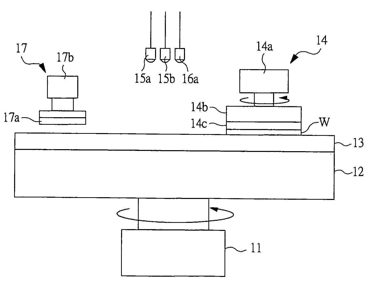
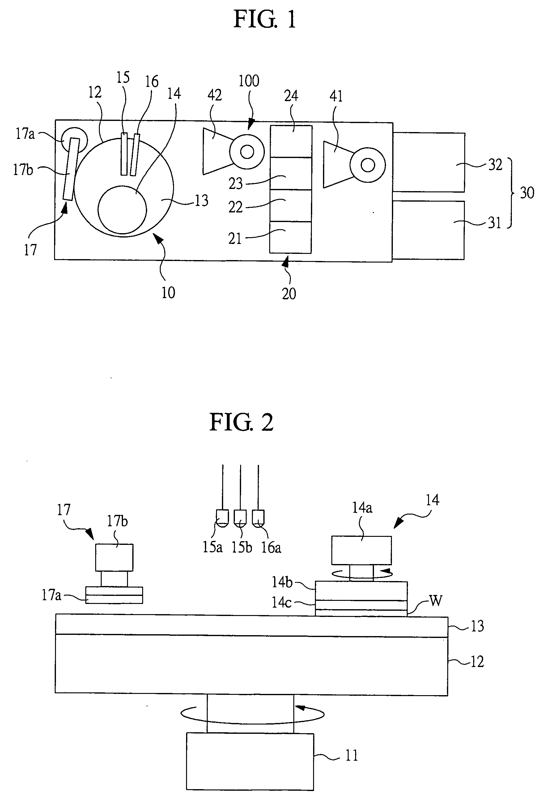
[0051]FIG. 1 is a plan view schematically showing the entirety of a CMP apparatus having a single-platen structure, which is used in an embodiment of the present invention. FIG. 2 is a side view schematically showing a principal portion of a polishing unit in a CMP apparatus.

[0052] A CMP apparatus 100 having a single-platen structure is provided with, as shown in FIG. 1, a polishing unit 10 and a cleaning unit 20 therein. In addition to them, a carrying-in / out unit 30 for reception and delivery of a wafer from and to the outside of the apparatus is also provided. Inside the apparatus, as shown in FIG. 1, robots 41 and 42 are provided for reception and delivery of the wafer between the cleaning unit 20 and the carrying-in / out unit 30 an...

second embodiment

[0090] (Second Embodiment)

[0091] In a second embodiment, unlike the structure described in the above first embodiment, description will be made of a CMP process in which a process of cleaning the polishing pad is provided between the process of the first layer metal film polishing and the process of the second layer metal film polishing. With the process of cleaning the polishing pad, the continuous CMP can be performed using the slurry for the second layer metal film polishing, which is completely different in its property from the slurry for the first layer metal film polishing. This CMP can be performed using the CMP apparatus 100 described in the first embodiment.

[0092]FIG. 5B is a flow diagram showing a processing procedure of the CMP described in the present embodiment. The first layer metal film is polished in the following manner, as shown in FIG. 5B. That is, the slurry for the first layer metal film polishing is supplied from the slurry supply port 15a onto the polishing ...

third embodiment

[0109] (Third Embodiment)

[0110] In the first and second embodiments, description has been made of the continuous CMP in which the wafer is in contact with the polishing pad and is continuously in a polishing state during the process of the first layer metal film polishing to the second layer metal film polishing. However, in a third embodiment, description will be made of the case where a process of temporarily retracting the wafer from the polishing pad is interposed after the process of the first layer metal film polishing is completed and before the process of the second layer metal film polishing is started.

[0111]FIG. 5C is a flow diagram showing a processing procedure of the CMP described in the present embodiment. The first layer metal film is polished in the following manner, as shown in FIG. 5C. That is, the slurry for the first layer metal film polishing is supplied from the slurry supply port 15a onto the polishing pad 13 rotated at the predetermined number of rotations t...


PUM


Abstract

The CMP of laminated heterogeneous metal films is efficiently improved without changing the structure of a conventional CMP apparatus. The CMP of a portion where heterogeneous metal films are laminated is performed on the same platen of a CMP apparatus having a single-platen structure. These heterogeneous metal films are a first layer metal film made of a wiring conductive metal such as Cu, and a second layer metal film made of a barrier film conductive metal such as Ti or Ta. After the CMP of the first layer metal film by using a slurry for polishing the first layer metal film is performed, the wafer is retracted from a polishing pad within a polishing unit of the CMP apparatus. With this state, the polishing pad is cleaned and then the retracted wafer is returned. Then, the CMP of the second layer metal film is performed by supplying a slurry for polishing the second layer metal film. By providing the process of cleaning the polishing pad between the process of polishing of the first layer metal film and the process polishing of the second layer metal film, the CMP can be efficiently performed with a single-platen structure even if the slurry for polishing the first layer metal film and the slurry for polishing the second layer metal film have much different properties.

Description

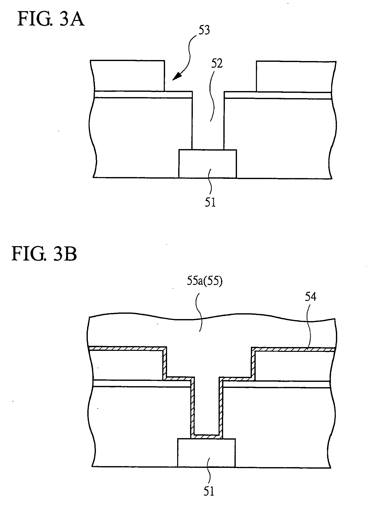
CROSS-REFERENCE TO RELATED APPLICATION [0001] The present application claims priority from Japanese patent application No. JP 2003-282140 filed on Jul. 29, 2003, the content of which is hereby incorporated by reference into this application. BACKGROUND OF THE INVENTION [0002] The present invention relates to a technique for manufacturing a semiconductor device and, more particularly, to a technique effectively applied to a Chemical Mechanical Polishing (CMP) process of a wiring metal film and a barrier metal film that are laminated mutually. [0003] As a wiring technique in a method of manufacturing a semiconductor device, there is a technique for performing, by using slurry, the CMP of a barrier conductive metal film made of tantalum (Ta), titanium (Ti), or the like and a wiring conductive metal film made of copper (Cu) or the like that is laminated on the barrier conductive metal film. [0004] In such CMP of the laminated metal films, a first layer metal film (an upper-layer metal f...

Claims


Application Information

Patent Timeline
IPC IPC(8): B24B37/00H01L21/304H01L21/321H01L21/4763H01L21/768
CPCB24B37/042H01L21/7684H01L21/3212
Inventor HAKATA, KATSUHIRO
Owner TRECENTI TECHNOLOGIES INC
Learn More