Human Energy Transduction and Storage System Having a One-Way Clutch

a technology of energy transduction and storage system and clutch, which is applied in the field of system and making use of energy, can solve the problems of less efficient use of energy applied to the crank at the rotational position of the crank other than the three o'clock position to do work, and achieve the effects of maximizing power supply, less efficient doing work, and improving efficiency

Inactive Publication Date: 2010-05-06
WILLS PETER LAWRENCE
View PDF19 Cites 13 Cited by
  • Summary
  • Abstract
  • Description
  • Claims
  • Application Information

AI Technical Summary

Benefits of technology

[0014]Crank and eccentric operated mechanisms find various application in many tools and machines. In the instance where such mechanisms are powered by hand or foot, the ability of the operator to deliver power through the crank or eccentric varies according to the position of the crank or eccentric. One example of a crank operated machine is a bicycle where the rider operates a pedal driven crank which transfers force to at least one of the bicycle wheels. However, the force transfer affected by the rider varies as a product of the rotational position of the crank, with, as stated above, the maximum transfer of power occurring at the three o'clock position of t

Problems solved by technology

Consequently, the energy applied to the crank at rotational positions of the c

Method used


Image

  • Human Energy Transduction and Storage System Having a One-Way Clutch
  • Human Energy Transduction and Storage System Having a One-Way Clutch
  • Human Energy Transduction and Storage System Having a One-Way Clutch

Examples


Embodiment Construction

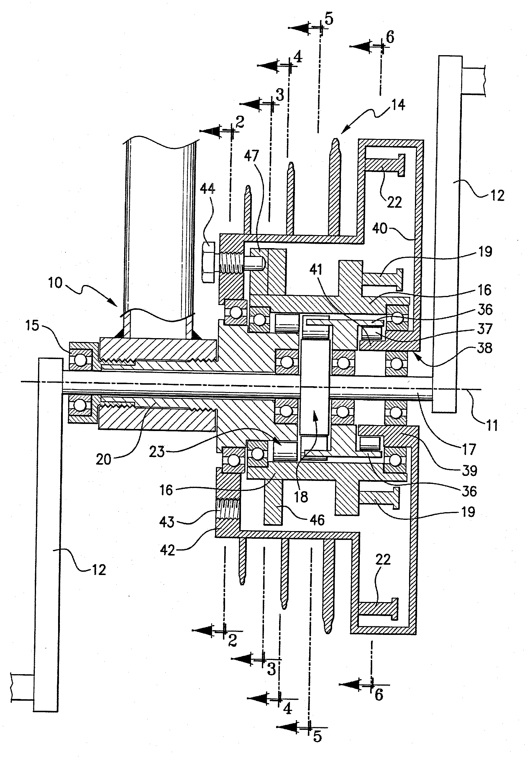
[0079]Referring to the drawings, FIG. 1 shows a cross-section through the bottom bracket 10 and along the pedal axis 11 of one embodiment of a device designed for use with a bicycle. In this embodiment, the device is fitted as an intermediate mechanical component between pedal cranks 12 and the chain wheel assembly or sprocket 14 of the bicycle crank set.

[0080]The pedal shaft 17 connecting the pedal cranks 12 is mounted by bearings 15 to the bicycle bottom bracket 10.

[0081]The device includes a rotatable primary driving hub 16 mounted for rotation about the pedal axis 11. The hub 16 is adapted to receive the driving force or torque applied to the pedal cranks 12 through pedals (not shown). The hub 16 is driven through a releasable primary clutch 18 which engages between the pedal shaft 17 and the hub 16, as shown particularly in FIG. 5. Thus, when the pedal shaft 17 is rotated by the cranks 12, the rotational movement is directly transferred to the hub 16 through the primary clutch ...


PUM


Abstract

An energy transduction and conservation system has a rotatable primary driving arrangement and a rotatable driven arrangement, the driving and driven arrangements cooperating through an energy storage arrangement. The driving arrangement supplies energy to the energy storage arrangement through a one-way driving system which blocks energy release from the energy storage arrangement back to the driving arrangement. Relative rotation of the driving arrangement is transferred to the energy storage arrangement through a first releasable clutch acting on a one-way rotatable hub whereby energy stored is released only through the driven arrangement. A further one-way clutch is actuated by a differential angular rotational speed to disconnect the first releasable clutch and drive the hub at the same time the energy storage arrangement drives the driven arrangement. The first releasable clutch includes release levers pivotally mounted to release the clutch and allows the inner body to rotate in the normally locking direction.

Description

BACKGROUND OF THE INVENTION[0001]This invention relates to an energy optimization system for enhancing the efficient use of human energy and relates particularly to a system and apparatus for making use of energy, particularly that derived from human endeavour, that might otherwise be wasted or used inefficiently.[0002]In one form, the invention is designed to make use of potential energy of a form of human endeavour where the potential energy may otherwise be unused or be used inefficiently. In another form, the invention is designed to conserve human energy in a physical activity where the energy is used to produce work. In a further form, the invention is designed to convert kinetic energy to potential energy and subsequently re-convert the potential energy back to kinetic energy.SUMMARY OF THE INVENTION[0003]In many tasks performed by humans in conjunction with machines or tools or other implements or aids, the effort employed by the human to move the tool or aid, or to drive th...

Claims


Application Information

Patent Timeline
IPC IPC(8): B62M1/10F16D41/00B62M3/08F16D41/066
CPCB62M1/10F16D3/12F16D41/066B62M1/105F16D41/08F16D41/26F16D47/04Y10T74/20888
Inventor WILLS, PETER LAWRENCE
Owner WILLS PETER LAWRENCE
Why Eureka
Try Eureka