Alleviation of aircraft landing gear loading using a brake control scheme

a technology of aircraft landing gear and control scheme, which is applied in the direction of braking system, braking components, transportation and packaging, etc., can solve the problems of high and achieve the effect of reducing reducing the dynamic loading of aircraft landing gear

Active Publication Date: 2010-05-06
THE BOEING CO
View PDF9 Cites 17 Cited by
  • Summary
  • Abstract
  • Description
  • Claims
  • Application Information

AI Technical Summary

Benefits of technology

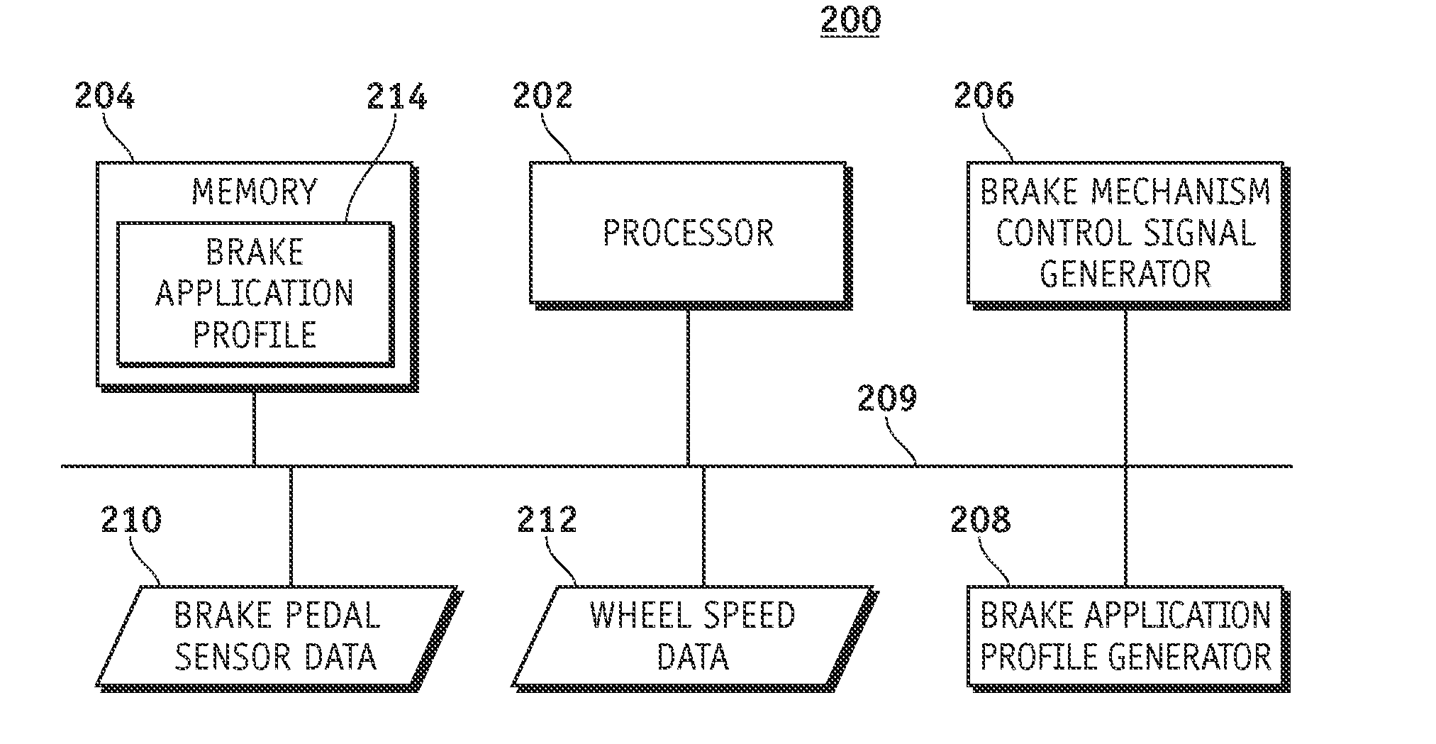
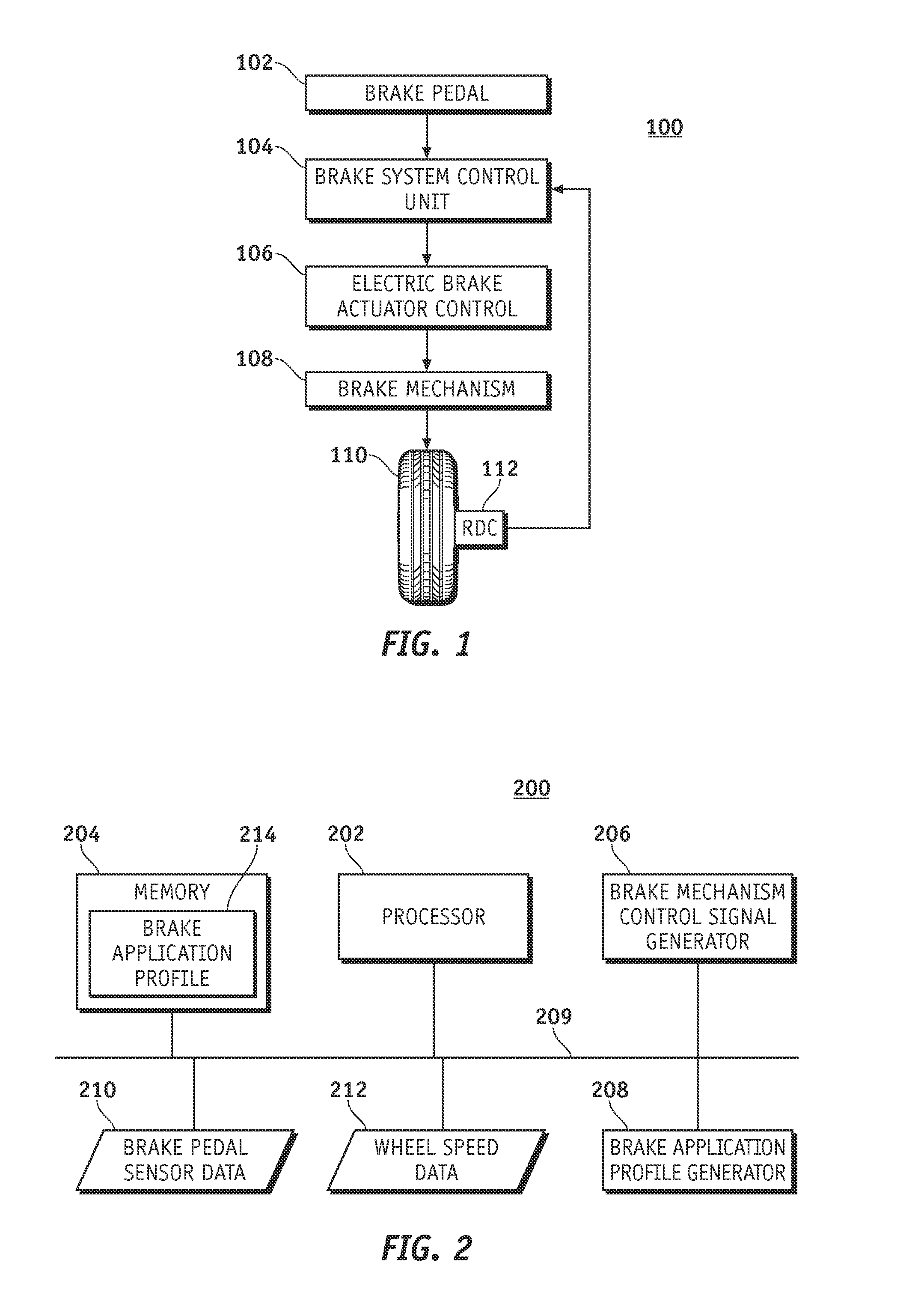
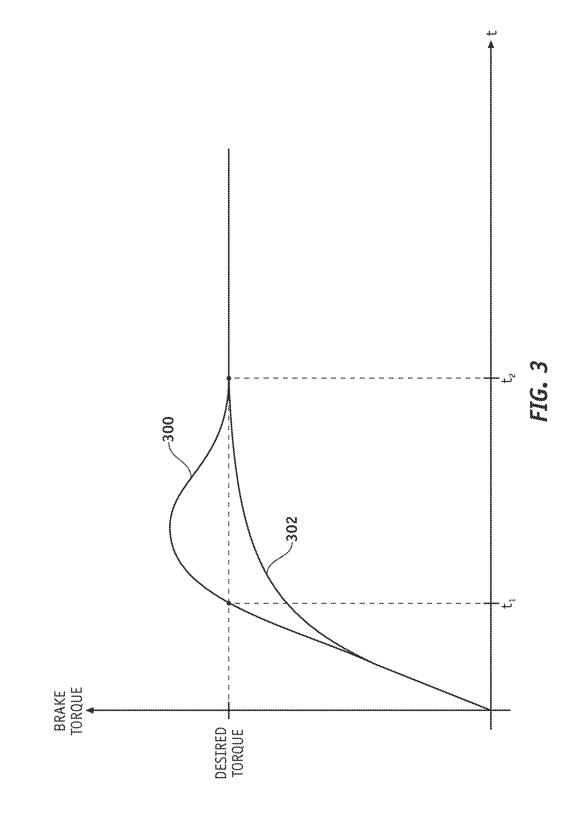
[0004]In one embodiment, an electric brake system for an aircraft controls the actuation of an aircraft brake mechanism in a manner that alleviates dynamic loading of the aircraft landing gear during braking The electric brake system varies the timing related to the onset of the desired brake torque in accordance with the measured speed of the aircraft, the amount of brake pedal deflection, and / or the rate of brake pedal deflection. The braking control scheme results in a smooth application of braking force rather than an abrupt and sudden application of braking force, which can result in high dynamic loading of the aircraft landing gear.

Problems solved by technology

The braking control scheme results in a smooth application of braking force rather than an abrupt and sudden application of braking force, which can result in high dynamic loading of the aircraft landing gear.

Method used


Image

  • Alleviation of aircraft landing gear loading using a brake control scheme
  • Alleviation of aircraft landing gear loading using a brake control scheme
  • Alleviation of aircraft landing gear loading using a brake control scheme

Examples


Embodiment Construction

[0014]The following detailed description is merely illustrative in nature and is not intended to limit the embodiments of the invention or the application and uses of such embodiments. Furthermore, there is no intention to be bound by any expressed or implied theory presented in the preceding technical field, background, brief summary or the following detailed description.

[0015]Embodiments of the invention may be described herein in terms of functional and / or logical block components and various processing steps. It should be appreciated that such block components may be realized by any number of hardware, software, and / or firmware components configured to perform the specified functions. For example, an embodiment of the invention may employ various integrated circuit components, e.g., memory elements, digital signal processing elements, logic elements, look-up tables, or the like, which may carry out a variety of functions under the control of one or more microprocessors or other ...


PUM


Abstract

An electric brake system for an aircraft employs a brake control process to alleviate high dynamic structural loading of the aircraft landing gear caused by braking maneuvers. The system obtains and processes real-time data—which may include the current aircraft speed, the current brake pedal deflection position, and the current brake pedal deflection rate—to determine how best to control the onset of the brakes. The braking control scheme delays the onset of the desired braking condition to reduce high dynamic loading and lurching of the aircraft.

Description

TECHNICAL FIELD[0001]Embodiments of the present invention relate generally to an electric brake system for an aircraft. More particularly, embodiments of the present invention relate to a brake control scheme that alleviates structural loading of aircraft landing gear.BACKGROUND[0002]The wheel brakes of an aircraft are controlled by the pilot after landing to assist in the ground deceleration of the aircraft. The wheel brakes can also be controlled by the pilot (or by a member of the ground crew) during ground taxi maneuvers. The large mass of an aircraft and the high landing speed results in very high momentum, which can translate to very high dynamic loads during braking maneuvers (especially when the brakes are applied suddenly). Consequently, aircraft landing gear are designed to withstand braking loads that are generated in response to the application of the aircraft wheel brakes. This design objective results in heavy and bulky landing gear assemblies.[0003]Hydraulic-based air...

Claims


Application Information

Patent Timeline
Patent Type & Authority Applications(United States)
IPC IPC(8): B60T8/32B60T8/86
CPCB60T8/00B60T8/1703B60T2220/04B64C25/00
Inventor GRIFFITH, T. TODD
Owner THE BOEING CO
Why Eureka
Try Eureka