

LED lighting circuit and illuminating apparatus using the same
- Summary
- Abstract
- Description
- Claims
- Application Information
AI Technical Summary
Benefits of technology
Problems solved by technology
Method used
Image

Examples
embodiment 1
Based on Fifth Viewpoint
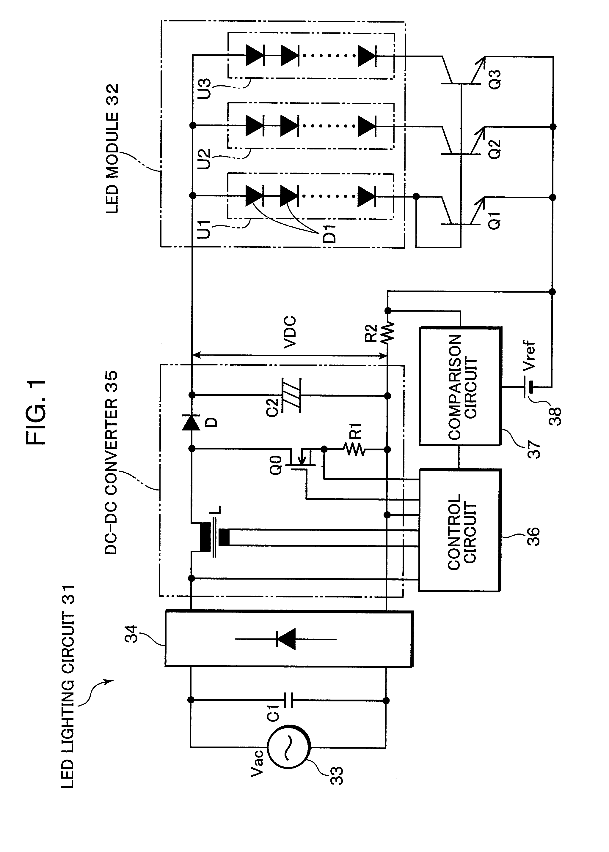
[0157]FIG. 22 is a block diagram showing a configuration of an LED lighting circuit 431 according to Embodiment 1 based on a fifth viewpoint of the present invention. In this LED lighting circuit 431, an LED module 32 is configured by connecting three LED load circuits U1 to U3 in parallel, each LED load circuit being made up of many serially connected LEDs D1. The number of series LED loads in each LED load circuit U1 to U3 is arbitrary and each LED load circuit may also be constructed of a single LED.
[0158]Each LED load circuit U1 to U3 is configured such that the LEDs D1 are mounted on and bonded to a common heat sink and a fluorescent substance for wavelength conversion and a light diffusion lens and the like are also attached. The LED module 32 and LED lighting circuit 431 are used as an illuminating apparatus, and emit blue or ultraviolet light as the LED load, convert, in wavelength, the light from the LED load using the fluorescent substance and emit ...
embodiment 2
Based on Fifth Viewpoint
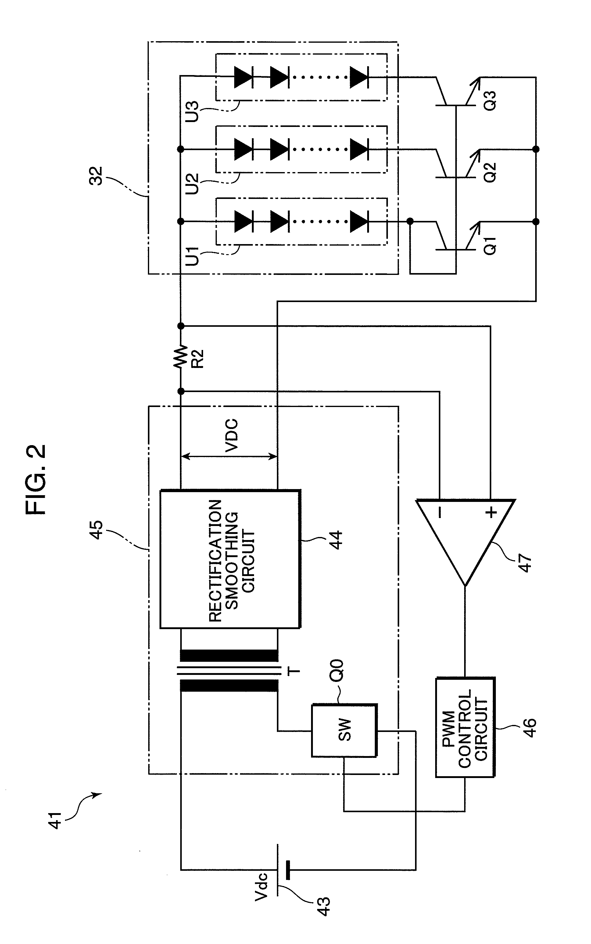
[0172]FIG. 25 is a block diagram showing a configuration of an LED lighting circuit 451 according to Embodiment 2 based on a fifth viewpoint of the present invention. In this LED lighting circuit 451, parts similar and corresponding to those of the aforementioned LED lighting circuit 431 are shown assigned the same reference numerals, and explanations thereof will be omitted. What should be noted is that in this LED lighting circuit 451, when a DC-DC converter 35 is subjected to constant current feedback control, a current detection resistor R2 thereof is inserted in the LED load circuit U1, which is the reference current creation circuit. In this case, loss at the resistor R2 can be reduced (in the example of FIG. 25, approximately ⅓ of loss in the example of FIG. 22). Furthermore, even if wire breakage occurs in LEDs D1 of any circuit other than the LED load circuit which becomes a reference, the remaining circuits can continue lighting with a constant curr...
embodiment 3
Based on Fifth Viewpoint
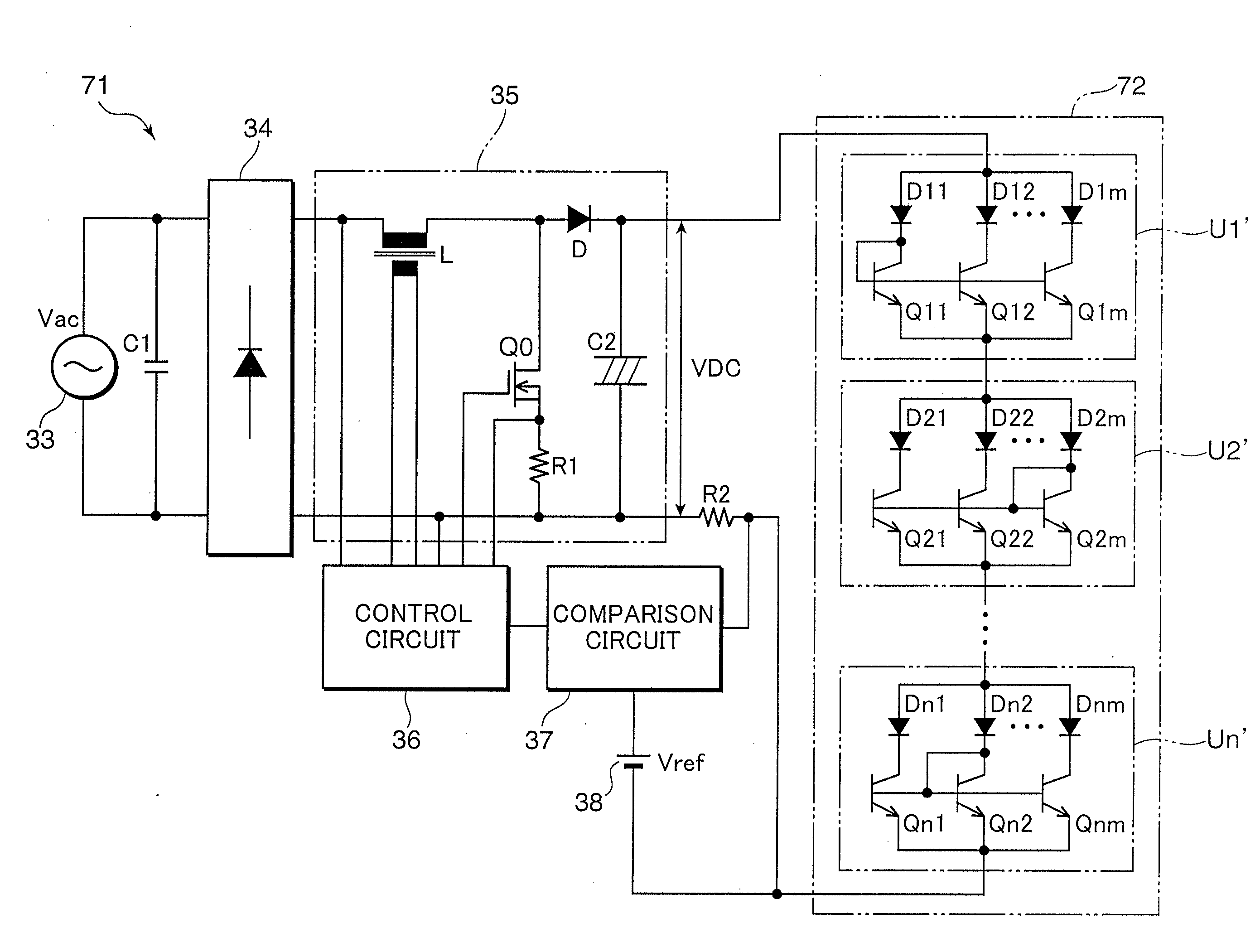
[0173]FIG. 26 is a block diagram showing a configuration of an LED lighting circuit 461 according to Embodiment 3 based on the fifth viewpoint of the present invention. In this LED lighting circuit 461, parts similar and corresponding to those in the aforementioned LED lighting circuit 431 are shown assigned the same reference numerals, and explanations thereof will be omitted. What should be noted is that in this LED lighting circuit 461, control elements Q2′ and Q3′ corresponding to the LED load circuits U2 and U3 other than the LED load circuit U1, which is the reference current creation circuit, are provided with switches SW42 and SW43 whereby, when the wire breakage detection circuit 442 detects wire breakage of the LED load circuit U1, which is the reference current creation circuit, the switch switching control circuit 462 can switch the corresponding control elements QT and Q3′ to a diode connection.
[0174]Therefore, in response to the occurrence of wi...
PUM
 Abstract
Description
Claims
Application Information