Branching filter

Active Publication Date: 2010-05-06
MURATA MFG CO LTD
View PDF10 Cites 29 Cited by
  • Summary
  • Abstract
  • Description
  • Claims
  • Application Information

AI Technical Summary

Benefits of technology

[0008]To overcome the problems described above, preferred embodiments of the present inven

Problems solved by technology

Unfortunately, for example, when many attenuation poles are provided by an increased number of parallel arms each having a parallel arm resonat

Method used


Image

  • Branching filter
  • Branching filter
  • Branching filter

Examples


first preferred embodiment

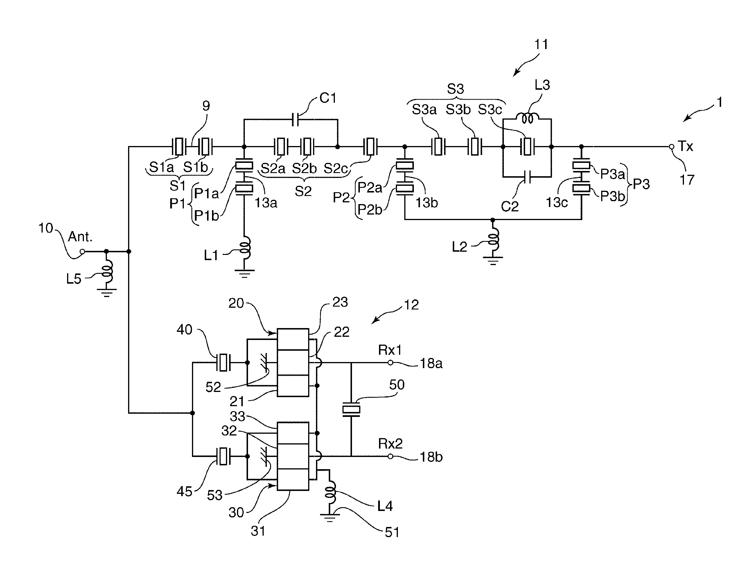
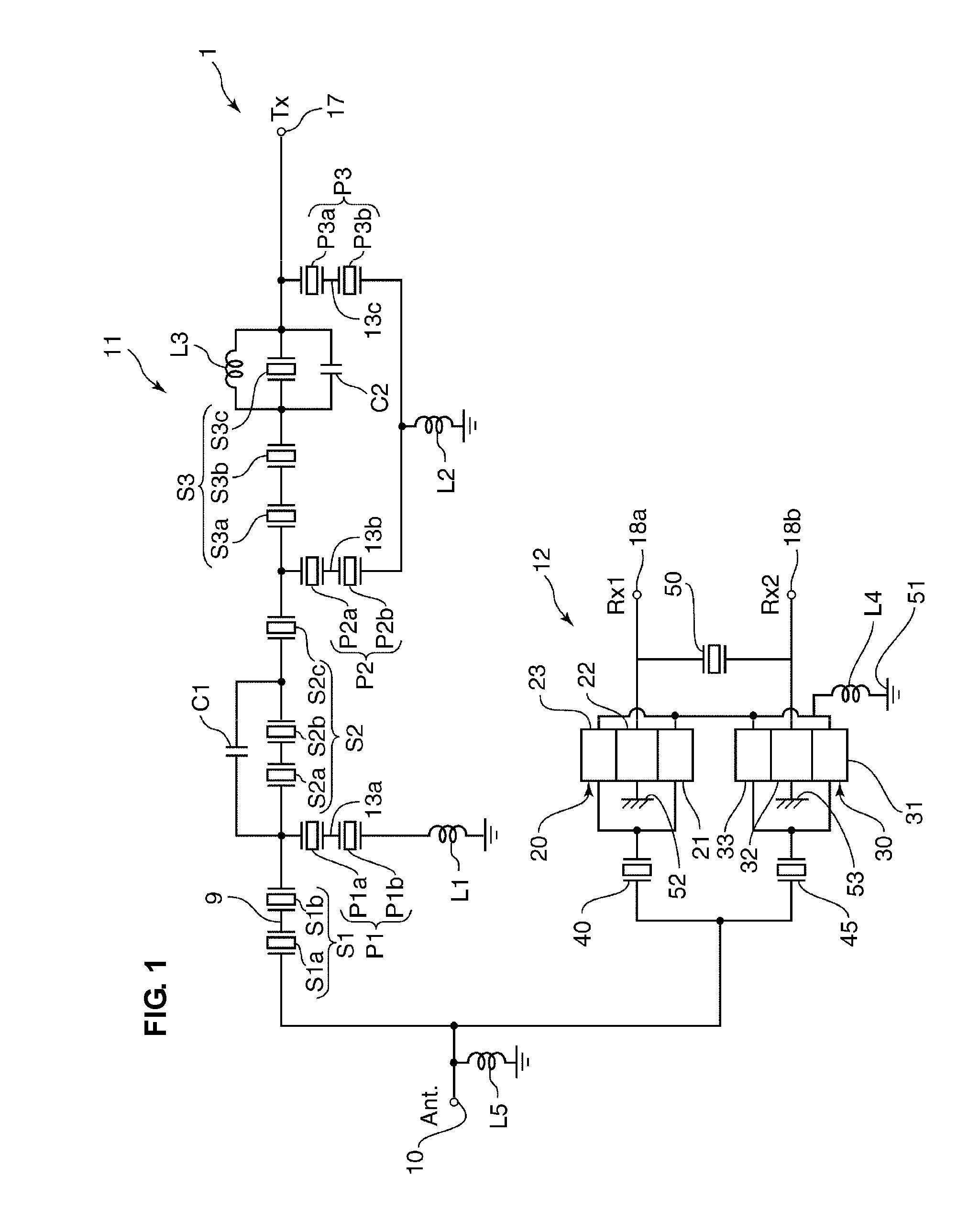
[0023]FIG. 1 is a circuit diagram of a branching filter according to a first preferred embodiment of the present invention. As illustrated in FIG. 1, a branching filter 1 according to the present preferred embodiment includes a transmission filter element 11 and a reception filter element 12. The reception filter element 12 is disposed between an antenna terminal 10 and each of a first reception signal terminal 18a and a second reception signal terminal 18b. The transmission filter element 11 is disposed between the antenna terminal 10 and a transmission signal terminal 17. An inductor L5 is connected between a ground potential and a node of the antenna terminal 10, the transmission filter element 11, and the reception filter element 12.

[0024]In the present preferred embodiment, an example is described in which each of the transmission filter element 11 and the reception filter element 12 is preferably a filter that utilizes a surface acoustic wave. However, the present invention is...

example 1

[0053]The branching filter 1 having the structure illustrated in FIGS. 1 and 2 and enabling Rayleigh waves to be excited was produced as described below, and the insertion loss of the transmission filter element 11 occurring when a signal was input from the transmission signal terminal 17 to the antenna terminal 10 was measured.

[0054]In the production of the transmission filter element 11, first, a silicon dioxide (SiO2) film having a thickness of approximately 190 nm defining a previous film was formed on a lithium niobate (LiNbO3) substrate having a cut angle of approximately 126.0°. Then, a groove corresponding to the shape of an electrode structure was formed on the previous film. In the groove, a nickel-chromium (NiCr) film (with a thickness of approximately 10 nm), a platinum (Pt) film (with a thickness of approximately 60 nm), a titanium (Ti) film (with a thickness of approximately 10 nm), an aluminum (Al) film (with a thickness of approximately 90 nm), and a Ti film (with a ...

second preferred embodiment

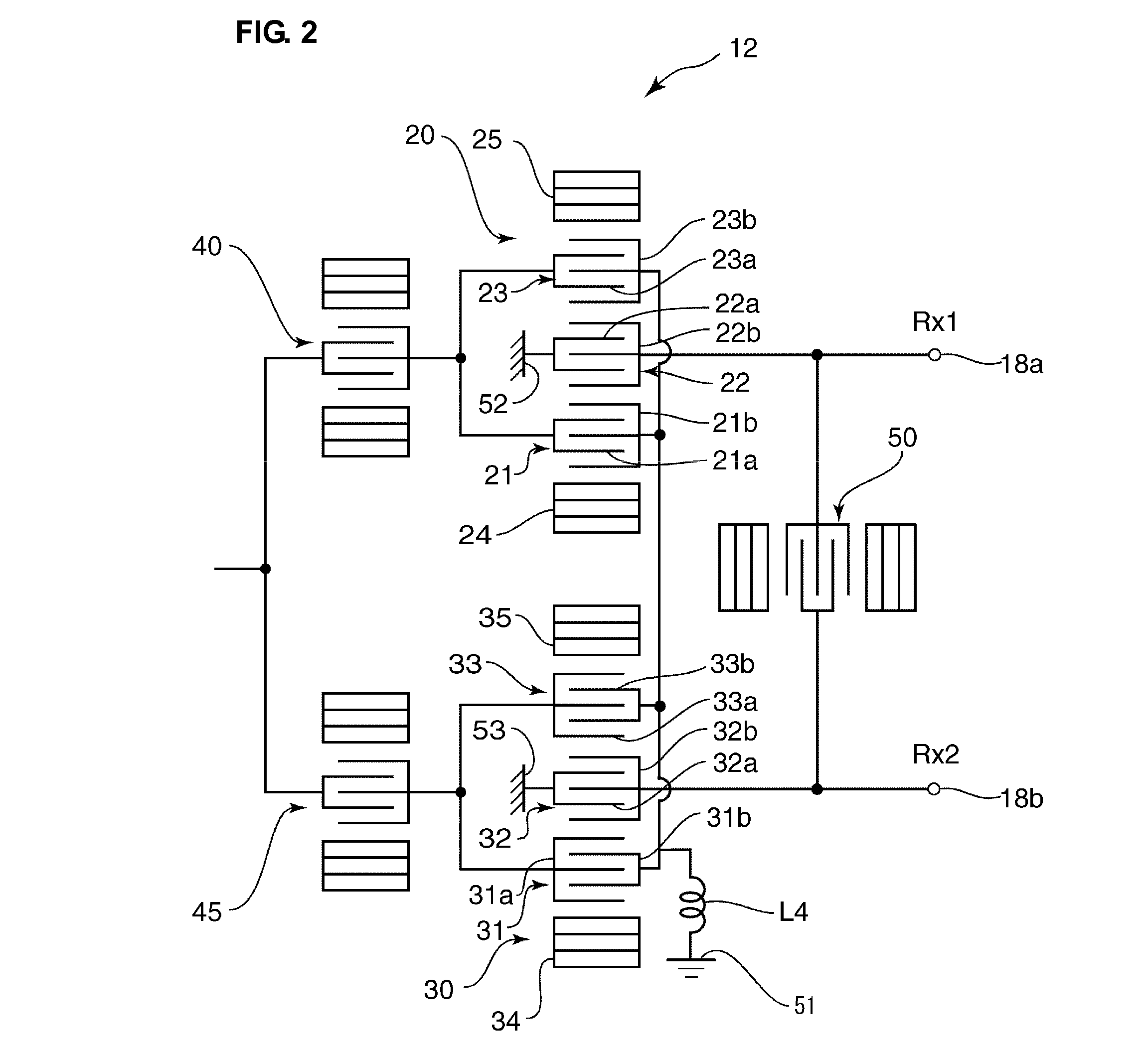
[0104]In the first preferred embodiment, an example is described in which the inductor L4, the comb electrode 22a of the second IDT electrode 22, and the comb electrode 32a of the second IDT electrode 32 are connected to different ground electrodes. However, the present invention is not limited to that example. For example, as illustrated in FIG. 6, the inductor L4, the comb electrode 22a of the second IDT electrode 22, and the comb electrode 32a of the second IDT electrode 32 may be connected to the same ground electrode 51.

[0105]Even in this case, similar to the above first preferred embodiment, as a transmission characteristic of the transmission filter element 11, a new attenuation range can be provided in a region higher than the pass band of the transmission filter element 11. Accordingly, the number of attenuation ranges that the transmission filter element 11 needs to provide can be reduced. Thus, the number of parallel arms in the transmission filter element 11 can be reduc...


PUM


Abstract

A branching filter includes an antenna terminal, a transmission signal terminal, a reception signal terminal, a transmission filter element, and a reception filter element. At least one of the transmission filter element and the reception filter element includes a longitudinally coupled resonator filter element having first and second IDT electrodes arranged along a direction of propagation of an elastic wave. The first IDT electrode includes a first end connected to the antenna terminal. The second IDT electrode includes a first end connected to one of the transmission signal terminal and the reception signal terminal. The longitudinally coupled resonator filter element further includes an inductor connected in series between a second end of the first IDT electrode and a ground potential.

Description

BACKGROUND OF THE INVENTION[0001]1. Field of the Invention[0002]The present invention relates to branching filters and, in particular, to a branching filter including a transmission filter element and a reception filter element that are connected to an antenna terminal.[0003]2. Description of the Related Art[0004]The demand for miniaturization in portable communication terminals is increasing, so it is highly desired to reduce the size of a branching filter for use in a portable communication terminal.[0005]As small branching filters, branching filters including surface acoustic wave (SAW) resonators are widely used. For example, Japanese Unexamined Patent Application Publication No. 2003-249842, which corresponds to U.S. Patent Application Publication No. 2004 / 0155730, discloses a branching filter that includes a ladder filter element having a plurality of SAW resonators as a transmission filter element and a longitudinally coupled resonator filter element as a reception filter ele...

Claims


Application Information

Patent Timeline
IPC IPC(8): H03H9/72
CPCH03H9/725
Inventor TANAKA, NOBUHIRA
Owner MURATA MFG CO LTD
Why Eureka
Try Eureka