Wireless device including a multiband antenna system

Active Publication Date: 2010-05-06
IGNION SL
View PDF49 Cites 41 Cited by
  • Summary
  • Abstract
  • Description
  • Claims
  • Application Information

AI Technical Summary

Benefits of technology

[0158]The dielectric slab can be advantageously used to tune an intrinsic frequency of the antenna structure until a target ratio between said intrinsic frequency and the highest frequency of the lowest frequency region of operation of the antenna system is obtained, without requiring an increase in the dimensions of said radiating element.
[0159]The radioelectric performance of the antenna structure, and that of the resulting antenna system, can be adjusted by setting the appropriate degree of overlapping between the projections of said radiating

Problems solved by technology

However, the antenna system is usually expected to be small in order to occupy as little space as possible within the device, which then allows for smaller devices, or for the addition of more specific equipment and functionality into the device.
Furthermore, an antenna system has to be integrated into a device or in other words a wireless handheld or portable device has to be constructed such that an appropriate antenna system may be integrated therein which puts constraints by consideration of the mechanical fit, the electrical fit and the assembly fit.
It is well known that the performance of such antennas is limited, in terms of impedance bandwidth, efficiency and related parameters (gain, VSWR and so on) by the spacing between said radiating element and the ground plane layer: the shorter the distance between both, the smaller the impedance bandwidth and efficiency.
Therefore, these antenna systems typically exhibit a limited radioelectric performance in the frequency regions of operation.
A multiband antenna system is sensitive to any of the above mentioned aspects because they may alter the electromagnetic coupling between the different geometrical portions of the radiating element, which usually translates into detuning effects, degradation of the radioelectric performance of the antenna system and/or the radioelectric performance wireless device, and/or greater interaction with the us

Method used


Image

  • Wireless device including a multiband antenna system
  • Wireless device including a multiband antenna system
  • Wireless device including a multiband antenna system

Examples


Embodiment Construction

[0185]Further characteristics and advantages of the invention will become apparent in view of the detailed description of some preferred embodiments which follows. Said detailed description of some preferred embodiments of the invention is given for purposes of illustration only and in no way is meant as a definition of the limits of the invention, made with reference to the accompanying figures.

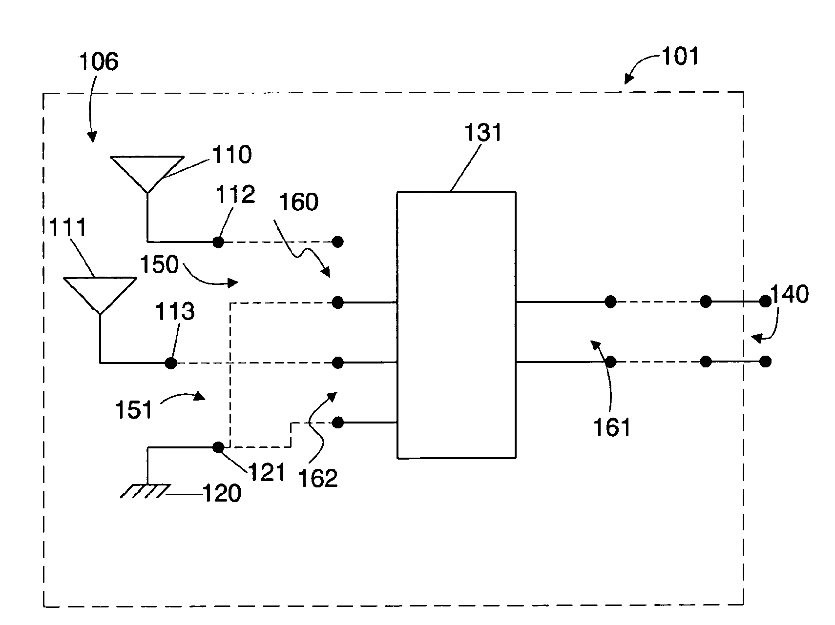
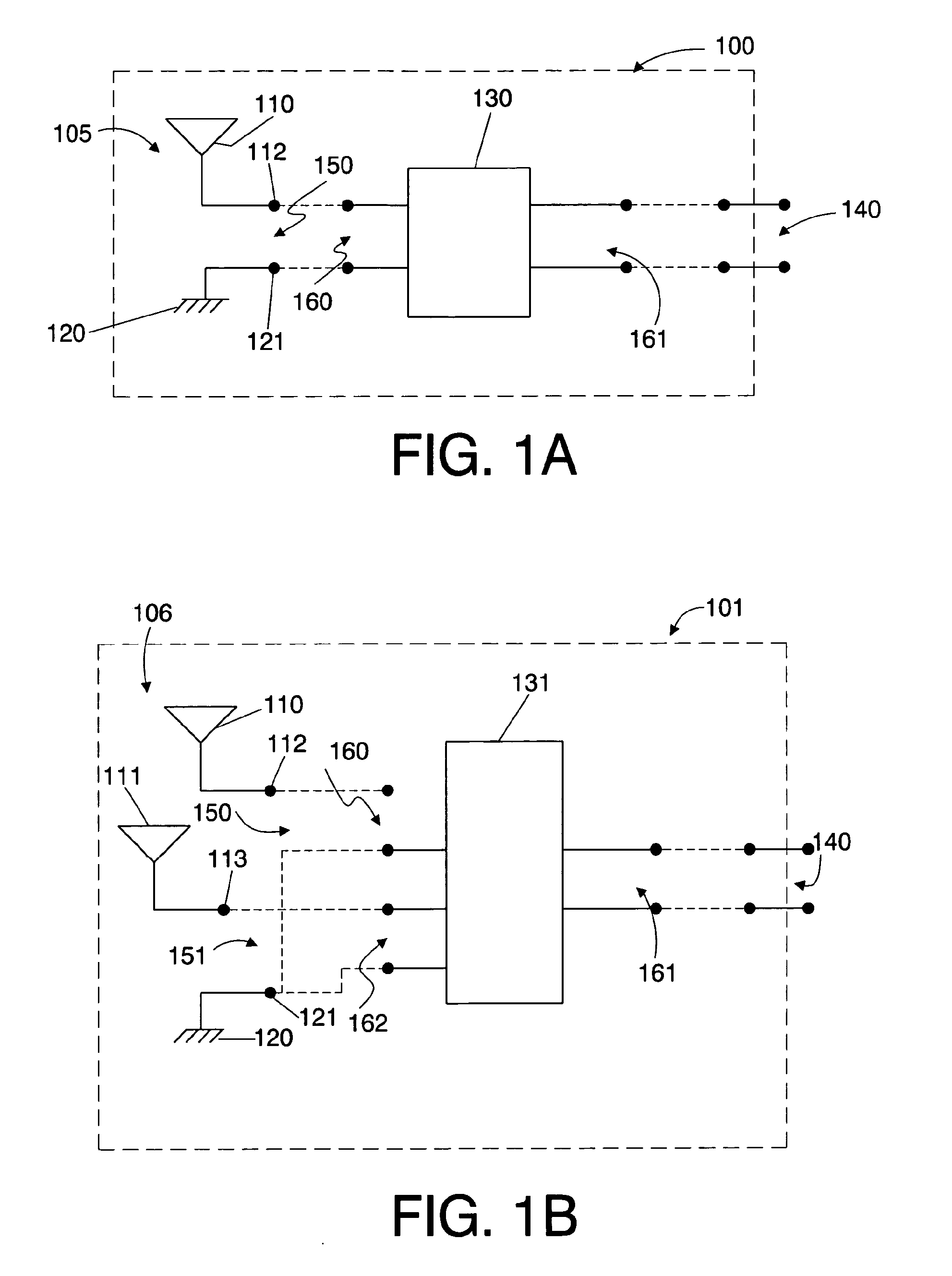
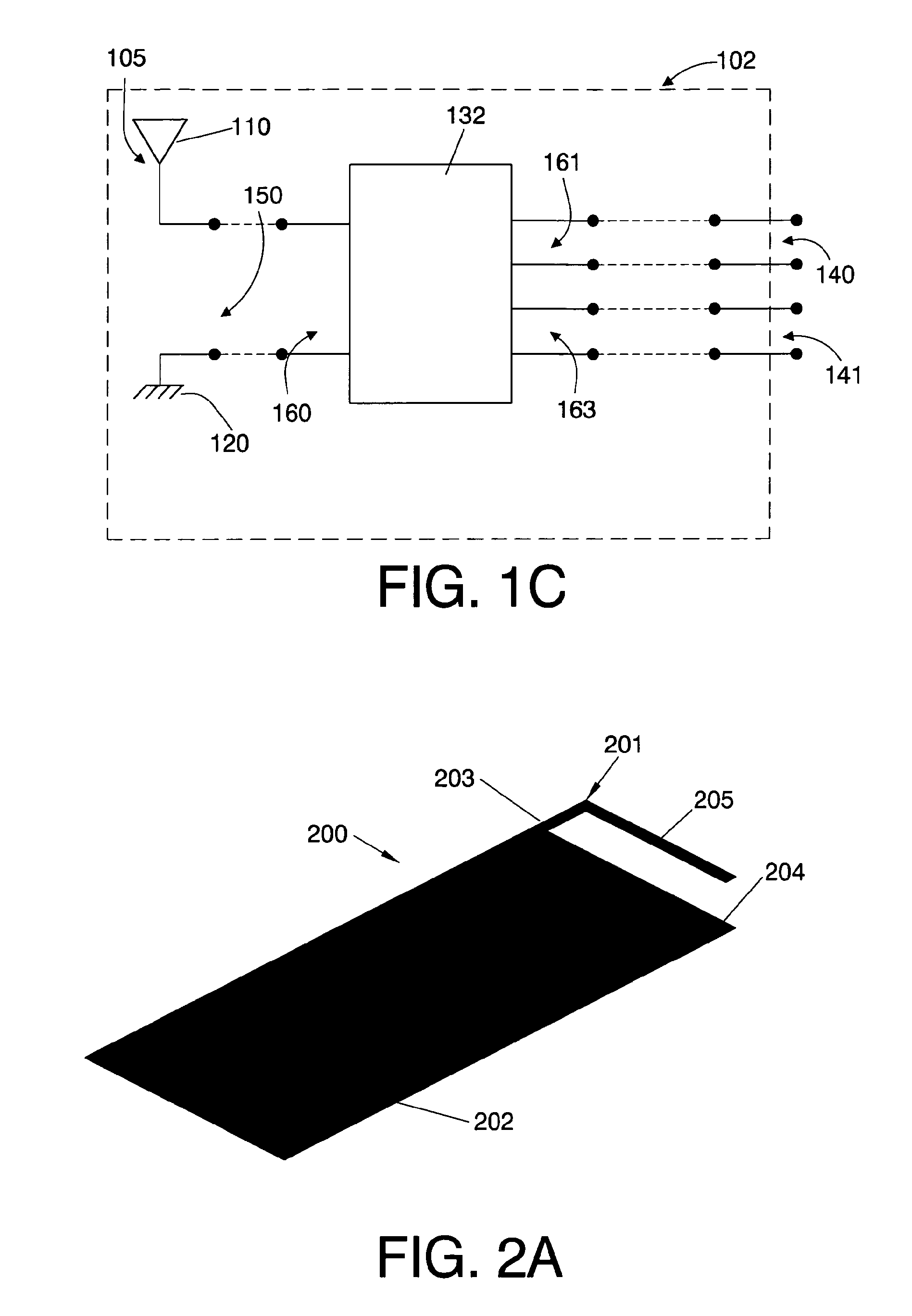
[0186]FIG. 1 shows the block diagram of three examples of an antenna system for a wireless handheld or portable device according to the present invention.

[0187]In particular FIG. 1a shows an antenna system 100 comprising an antenna structure 105, a matching and tuning system 130 and an external I / O port of the antenna system 140. The antenna structure 105 comprises a radiating element 110, which includes a connection point 112, and a ground plane layer 120, said ground plane layer including also a connection point 121. The antenna structure 105 further comprises an internal I / O port 150 defi...


PUM


Abstract

A wireless handheld or portable device includes an antenna system operative in a first frequency region and a higher, second frequency region that includes an antenna structure, a matching and tuning system, and an external input/output port. The antenna structure includes at least one radiating element including a connection point, a ground plane layer including at least one connection point, and at least one internal input/output port. At least one radiating element of the antenna structure protrudes beyond the ground plane layer. The antenna structure features at any of its at least one internal input/output ports when disconnected from the matching and tuning system an input return loss curve having a minimum at a frequency outside the first frequency region of operation of the antenna system. The matching and tuning system provides impedance matching to the antenna system in the first and second regions of operation of the antenna system.

Description

[0001]This international patent application claims priority to prior U.S. application No. 60 / 910,113 filed on 4 Apr. 2007 and to prior EP-application No. 07105364 filed on 30 Mar. 2007. The entire disclosures of the aforesaid application numbers U.S. 60 / 910,113 and EP 07105364 are hereby incorporated by reference.OBJECT OF THE INVENTION[0002]The present invention relates to the field of internal antennas for a wireless handheld device, and generally for any wireless portable device, to enable the transmission and reception of electromagnetic wave signals.[0003]It is an object of the present invention to provide an antenna system for a wireless handheld or portable device (such as for instance but not limited to a mobile phone, a smartphone, a PDA, an MP3 player, a headset, a USB dongle, a laptop computer, a gaming device, a digital camera, a PCMCIA or Cardbus 32 card), which occupies a reduced volume within the wireless device and is capable of operation in a plurality of frequency ...

Claims


Application Information

Patent Timeline
IPC IPC(8): H01Q1/50H01Q1/24H01Q5/10
CPCH01Q1/243H01Q1/36H01Q5/00H01Q1/48H01Q5/335H01Q5/50H01Q21/30
Inventor ANGUERA, JAUMESANZ, IVANPUENTE, CARLESMUMBRU, JOS
Owner IGNION SL
Why Eureka
Try Eureka