Liquid crystal display device

a display device and liquid crystal technology, applied in the direction of instruments, static indicating devices, etc., can solve the problems of enlargement of frame size, lowering of product value, and increase of power consumption of driver circuits, so as to achieve high quality display and low power consumption

Active Publication Date: 2010-05-06
KK TOSHIBA +1
View PDF10 Cites 22 Cited by
  • Summary
  • Abstract
  • Description
  • Claims
  • Application Information

AI Technical Summary

Benefits of technology

[0013]The present invention has been made to address the above mentioned problems. One object of the present invention is to provide a liquid crystal display device with a static memory in each pixel to achieve low power consumption and a high quality display.

Problems solved by technology

Since the voltages VLCa and VLCb are connected to a total liquid crystal capacitance of all the pixels in the display area, it is necessary to design driving circuits such as output buffers for voltages VLCa and VLCb so that a driving ability of output buffers is sufficiently high to enable voltages applied to the liquid crystal capacitance of all pixels invert simultaneously, which results in an increase in power consumption of the driver circuits.
Furthermore, when the driving circuits for the voltages VLCa and VLCb are formed in the array substrate using the same process as the pixels, the circuit size of the driving circuits becomes large and a large layout space is required, which may result in an enlargement of a frame size and further a lowering of a product value.
Otherwise, power consumption of a driver circuit for data lines may be increased.
Moreover, in this technology, a problem is noted that a current to maintain a pixel signal is not easily discharged when a power becomes on or off and an abrupt power failure occurred, which may result in generation of a display time lag.

Method used


Image

  • Liquid crystal display device
  • Liquid crystal display device
  • Liquid crystal display device

Examples


first embodiment

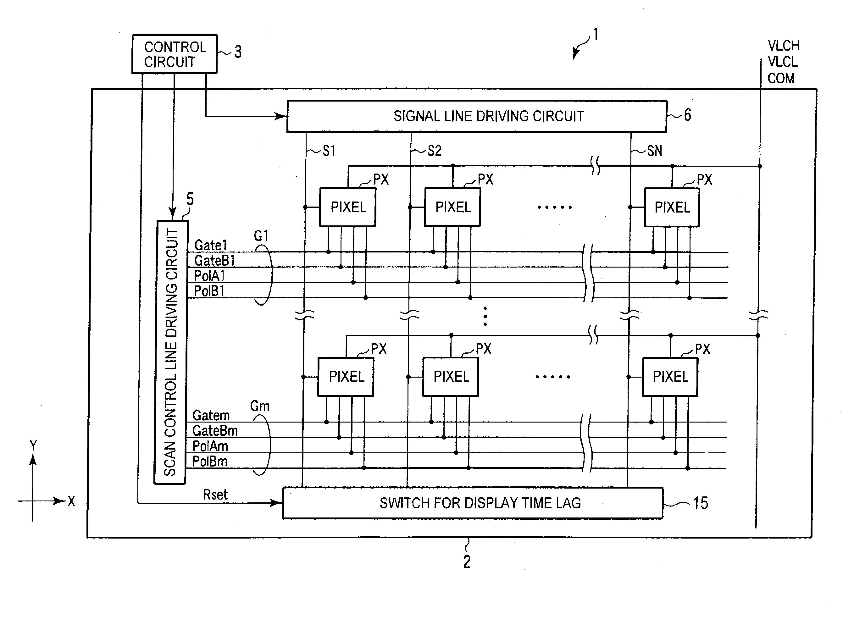
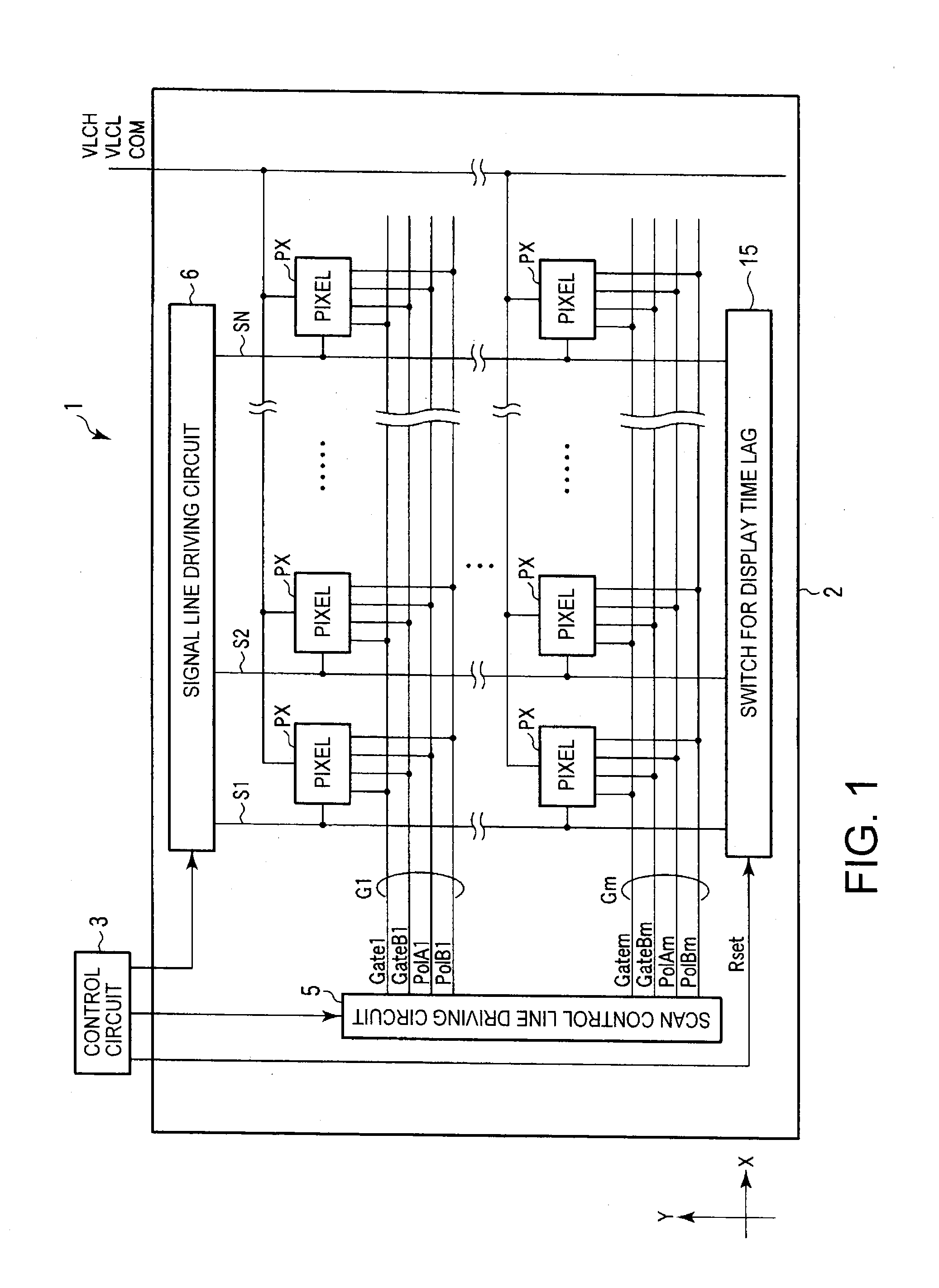
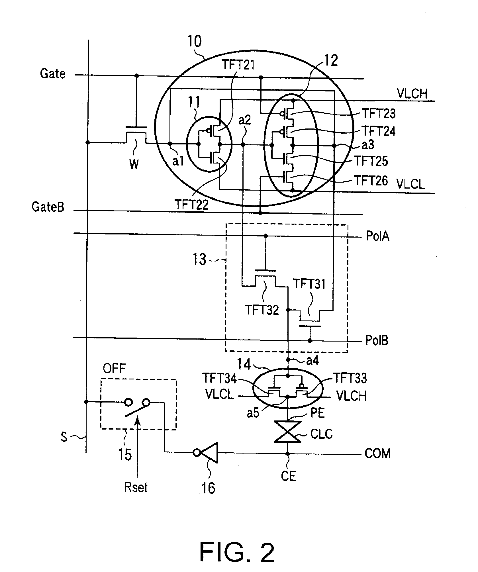
[0030]Hereinafter, a liquid crystal display device will be explained referring to figures. As shown in FIG. 1, the liquid crystal display device includes a display panel 1 and a control circuit 3 to control the display panel 1. The liquid crystal display panel 1 is formed of a pair of substrates, an array substrate 2 and a counter substrate (not shown) and a liquid crystal layer interposed therebetween. The display panel 1 includes (m×n) pixels PX arranged in a matrix on the array substrate 1 formed of a transmissive insulating substrate such as a glass substrate. The display panel 1 also includes first to mth scan control lines G1, . . . Gm composed of independently arranged 4 control lines and connected to the pixels arranged in a row direction. Each of the scan control lines G includes four control lines Gate, GateB, PolA and PolB to control the operation of the pixels PX.

[0031]The control circuit 3 controls a transmittance of the display panel 1 by a liquid crystal driving volt...

fourth embodiment

[0064]FIG. 11 shows a fourth embodiment according to the present invention, in which a digital gradation display system using an area coverage modulation method of displaying multiple gray levels is adopted. In the digital gradation display system, one pixel electrode PE is divided into a plurality of sub-pixel electrodes and respective areas of the sub-pixels are different from each other. One or some sub-pixel electrodes in the selected one pixel are selected to get a display area in one pixel by combining the sub-pixels. Accordingly, the display area in the selected pixel may be changed digitally.

[0065]FIG. 11 is a diagram showing respective size of sub-pixel electrodes of each pixel and a pattern of an arrangement of the sub-pixel electrodes. In this embodiment, 4 bits-16 retardations display is adopted. If the area of sub-pixel electrode P0 is “1”, the area of sub-pixel electrode P1 is double, P2 is four times and P3 is eight times. The 4 bits image data input to corresponding ...


PUM


Abstract

A liquid crystal display device includes a pair of substrates, a plurality of pixels arranged in a matrix and a static memory formed on the substrates. A bit signal corresponding to an image data is written and held in a static memory in the pixel. The polarity of the input bit signal is controlled. A liquid crystal voltage supplied to a liquid crystal layer arranged between the pair of substrates is generated by the bit signal. The polarity of the bit signal is controlled to alternate the liquid crystal voltage, and a transmittance of the liquid crystal layer is changed by supplying the alternated liquid crystal voltage.

Description

CROSS-REFERENCE TO RELATED APPLICATION[0001]This application is based upon and claims the benefit of priority from prior Japanese Patent Application No. 2008-279644 filed Oct. 30, 2008, and the entire contents of which are incorporated herein by reference.BACKGROUND OF THE INVENTION[0002]1. Field of the Invention[0003]The present invention relates to a liquid crystal display device including a pixel memory provided in each of LCD pixels to store an image data, and especially to control voltages applied to a pair of electrodes of respective pixels arranged in the liquid crystal display device.[0004]2. Description of the Background Art[0005]Liquid crystal display devices are widely used as typical display devices for various kinds of equipments such as personal computers, OA equipments, and TV sets because the display devices have many advantages such as lightness, compactness and low power consumption. In recent years, mobile liquid crystal display devices find use in mobile terminal...

Claims


Application Information

Patent Timeline
Patent Type & Authority Applications(United States)
IPC IPC(8): G09G3/36
CPCG09G3/3614G09G3/3648G09G2300/0809G09G2300/0823G09G2300/0857G09G2310/0245G09G2310/0262G09G2330/021G09G2330/027
Inventor HARADA, KENJI
Owner KK TOSHIBA
Why Eureka
Try Eureka