LED lighting unit and method for manufacturing the same

a technology of led lighting and led light, which is applied in the direction of semiconductor devices for light sources, light and heating apparatus, printed circuit aspects, etc., can solve the problems of difficult control of optical characteristics, difficult to avoid respective variability in distribution densities, and difficult for led lighting units to reliably emit, etc., to achieve high accuracy

Inactive Publication Date: 2010-05-06
STANLEY ELECTRIC CO LTD
View PDF17 Cites 35 Cited by
  • Summary
  • Abstract
  • Description
  • Claims
  • Application Information

AI Technical Summary

Benefits of technology

[0023]According to the exemplary LED lighting unit, the plurality of light-emitting portions that includes the first and the second cavity can be configured to include one kind of LED chip and one kind of encapsulating resin including a phosphor in the cavities. The optical characteristics of light emitted from the light-emitting portions can be controlled by changing thicknesses of the encapsulating resin based upon depths of the cavities. Thus, variability of optical characteristics such as the brightness, the wavelength distribution and the like can be reduced due to the simple structure, and therefore the LED lighting unit can emit light having a favorable color temperature while maintaining high color reproducibility.
[0027]According to the above-described method for manufacturing the LED lighting unit, the thicknesses of the encapsulating resins based upon the depths of the cavities can be formed with high accuracy using a simple manufacturing machine. In this case, the thicknesses of the encapsulating resins can also be adjusted individually using the mask plate. Thus, the manufacturing method can provide the various LED lighting units that can emit suitable lights having favorable color temperatures with stability for the lighting systems.

Problems solved by technology

However, it may be difficult to avoid causing respective variability in distributing densities between the epoxy resin and these different phosphors even when trying to control the respective accuracy of the different distributing densities within ranges of two predetermined accuracies in the mixing processes.
As the result, it may be difficult for the LED lighting unit to reliably emit light having a favorable color temperature because the color reproducibility with regard to the optical characteristics may be difficult to control even if the color temperature is controlled by the current control or the duty-ratio control.

Method used


Image

  • LED lighting unit and method for manufacturing the same
  • LED lighting unit and method for manufacturing the same
  • LED lighting unit and method for manufacturing the same

Examples


Embodiment Construction

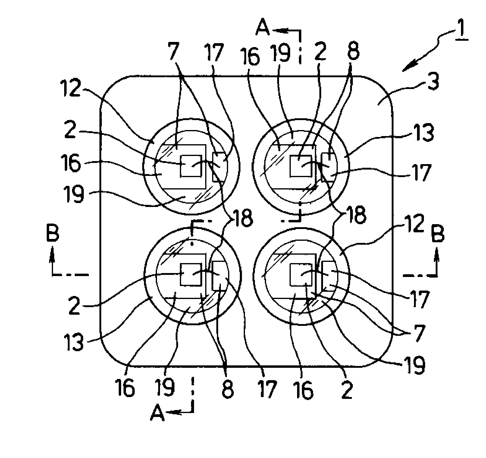
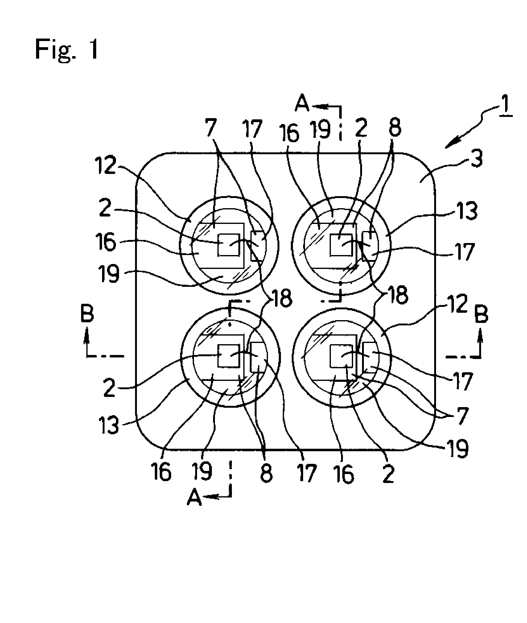
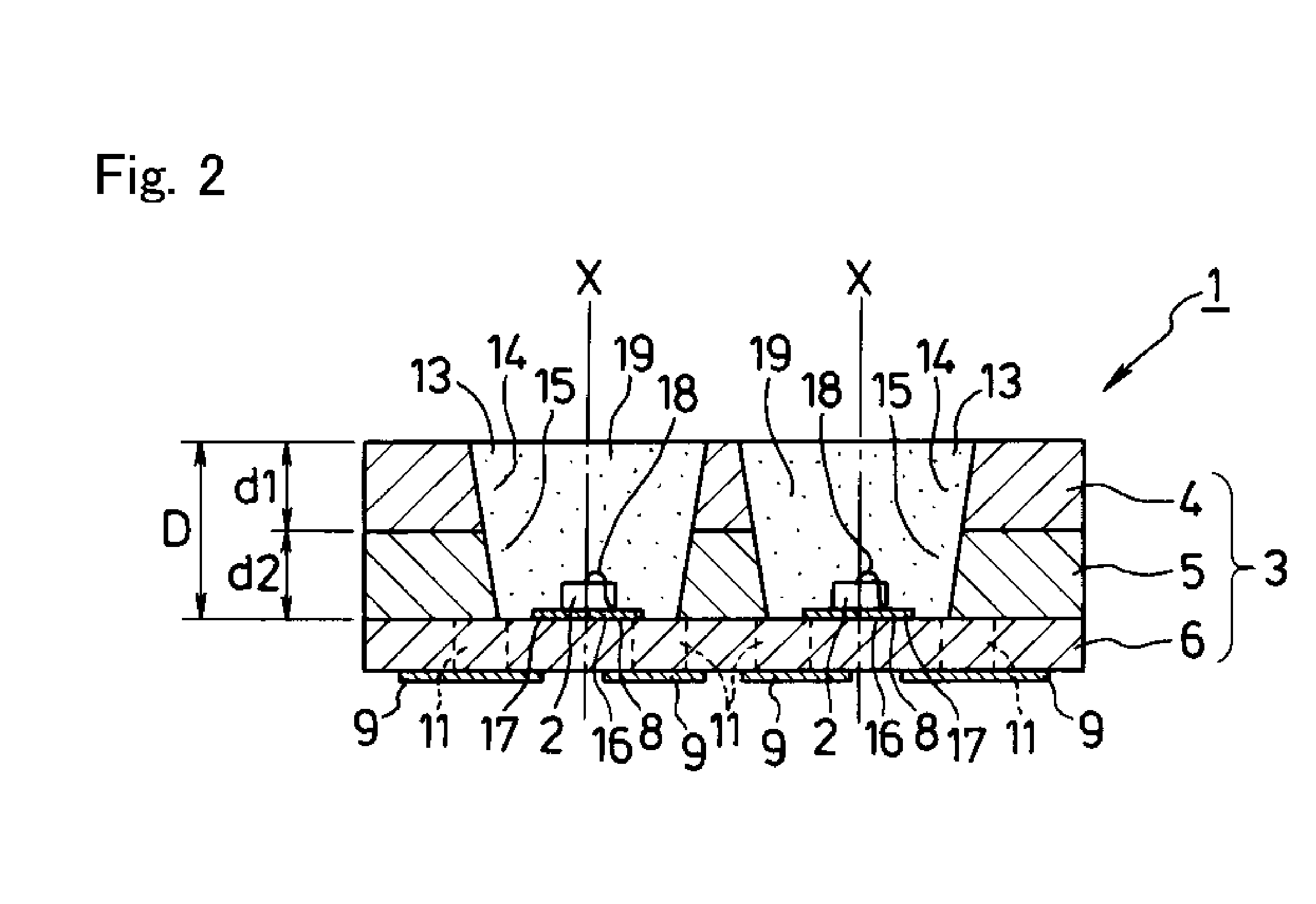
[0037]The disclosed subject matter will now be described in detail with reference to FIGS. 1 to 7. FIG. 1 is a top view showing an exemplary embodiment of an LED lighting unit made in accordance with principles of the disclosed subject matter, and FIGS. 2-3 are a cross-section view taken along line A-A as shown in FIG. 1 and a cross-section view taken along line B-B shown in FIG. 1, respectively. An LED lighting unit 1 can include a plurality of LED chips 2 and a casing 3 that includes the LED chips 2 mounted therein. The casing 3 can be composed of a laminate board, and the laminate board can be composed of an insulating material such as an epoxy resin, a polyimide, a ceramic, etc.

[0038]The casing 3 can include: a first insulating board 6 having a first surface and a second surface; a second insulating board 5 having a first surface and a second surface and through-bores 15, the second surface thereof located adjacent and possibly in direct contact with the first surface of the fir...


PUM


Abstract

An LED lighting unit and a method for manufacturing the same can include a first cavity and a second cavity which has a depth that is different from that of the first cavity. The first and the second cavities can include an LED chip and an encapsulating resin including a phosphor. Color temperatures of light emitted from these cavities can be controlled by changing thicknesses of the encapsulating resin based on the depth of each of these cavities so as to be located on a substantially black body, and the variability of the optical characteristics can be reduced due to the simple structure. Thus, the LED lighting unit can emit light having a favorable color temperature that is close to a natural light using light that is emitted from these cavities. The manufacturing method can include forming the thickness of the encapsulating resin with accuracy, and therefore can provide a suitable LED lighting unit for various lighting systems.

Description

[0001]This application claims the priority benefit under 35 U.S.C. §119 of Japanese Patent Application No. 2008-279991 filed on Oct. 30, 2008, which is hereby incorporated in its entirety by reference.BACKGROUND[0002]1. Field[0003]The presently disclosed subject matter relates to LED lighting units and to a manufacturing method for these LED lighting units, and more particularly to the LED lighting units having a favorable color temperature in which a plurality of light-emitting portions includes the respective LED chips and a phosphor, and to the manufacturing method for these lighting units.[0004]2. Description of the Related Art[0005]Lighting units having various color temperatures have been commercialized in order to meet customer's needs such as matching an illuminating light to interior decorating and atmosphere in a room. The color temperatures include a wide range from a white light of cool color such as a natural light in daytime to a warm color such as light from a light b...

Claims


Application Information

Patent Timeline
Patent Type & Authority Applications(United States)
IPC IPC(8): F21V9/16H01L33/00H01L21/00
CPCF21K9/00H01L25/0753H01L33/50H01L33/60H05K1/0298H05K1/183H05K3/284H05K2201/10106H01L2224/48091H01L2224/48227H01L2924/00014H01L2924/00H01L2924/181H01L2924/00012
Inventor NAKAJIMA, TOSHIYUKI
Owner STANLEY ELECTRIC CO LTD
Why Eureka
Try Eureka