
Temperature sensing circuit using CMOS switch-capacitor

Inactive Publication Date: 2010-05-06
ADVANCED ANALOG TECH INC
View PDF12 Cites 15 Cited by
  • Summary
  • Abstract
  • Description
  • Claims
  • Application Information

AI Technical Summary

Problems solved by technology

As such, when an integrated circuit configured with a large number of transistors operates at a high clock rate, the amount of heat dissipated will be enormous to the extent that the operating temperature may exceed 100 degrees centigrade.
Due to the change in temperature, all components in the chip will be adversely affected, since temperature and conductivity have an inversely proportional relationship.
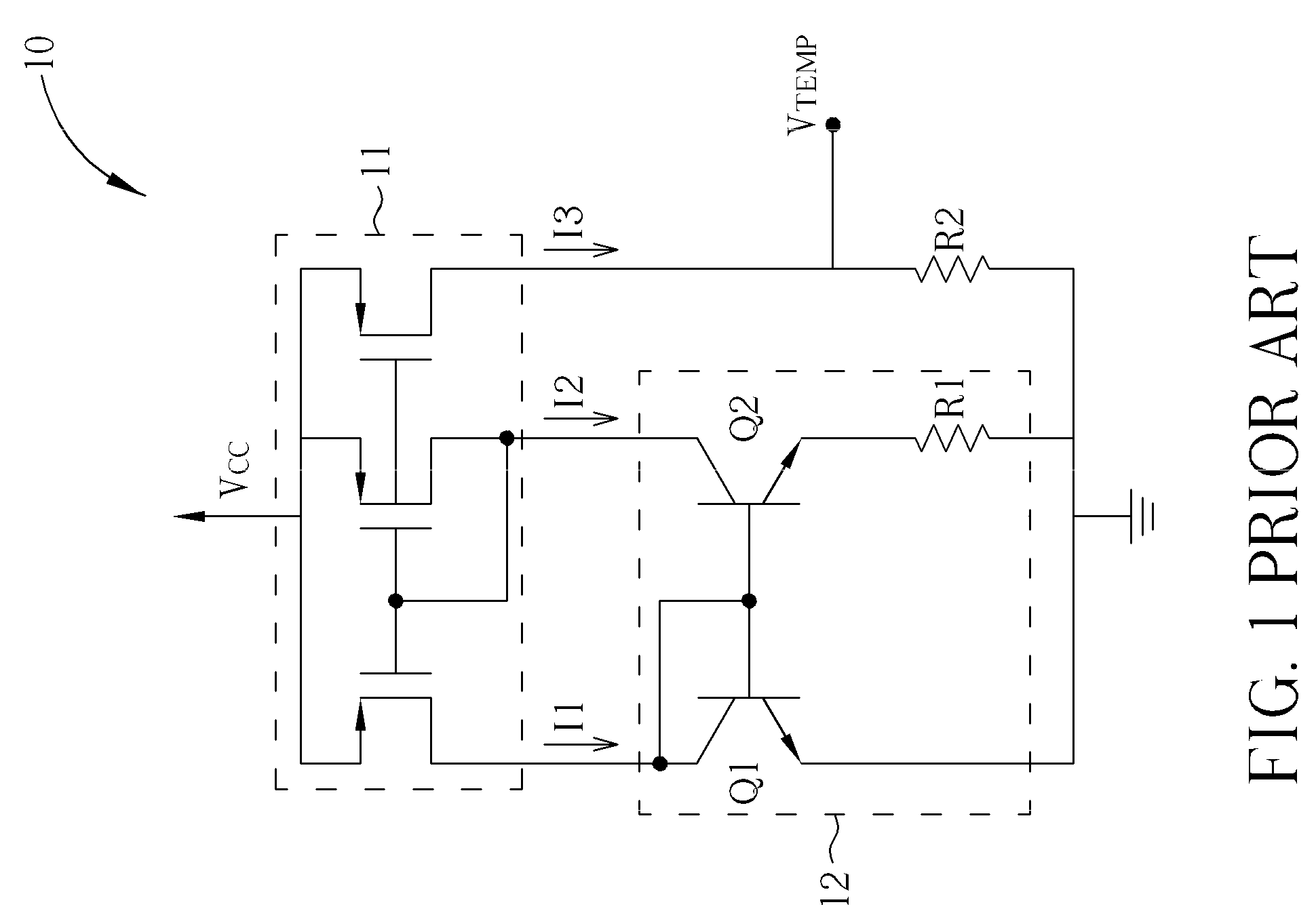
If manufacture of the transistors Q2 and Q1 is based simply on the calculated values, the outcome will be a mismatch in the current gains 13 of the transistors Q2 and Q1, thereby resulting in failure of the temperature sensing circuit 10 to operate normally and inability of the temperature sensing circuit 10 to serve the purpose of temperature measuring.
However, in view of manufacturing constraints, it is known that the resistance values of resistors cannot be accurately controlled.
Due to the requirement of a high resistance ratio R2 / R1, the resultant error tends to be too high.

Method used


Image

  • Temperature sensing circuit using CMOS switch-capacitor
  • Temperature sensing circuit using CMOS switch-capacitor
  • Temperature sensing circuit using CMOS switch-capacitor

Examples


Embodiment Construction

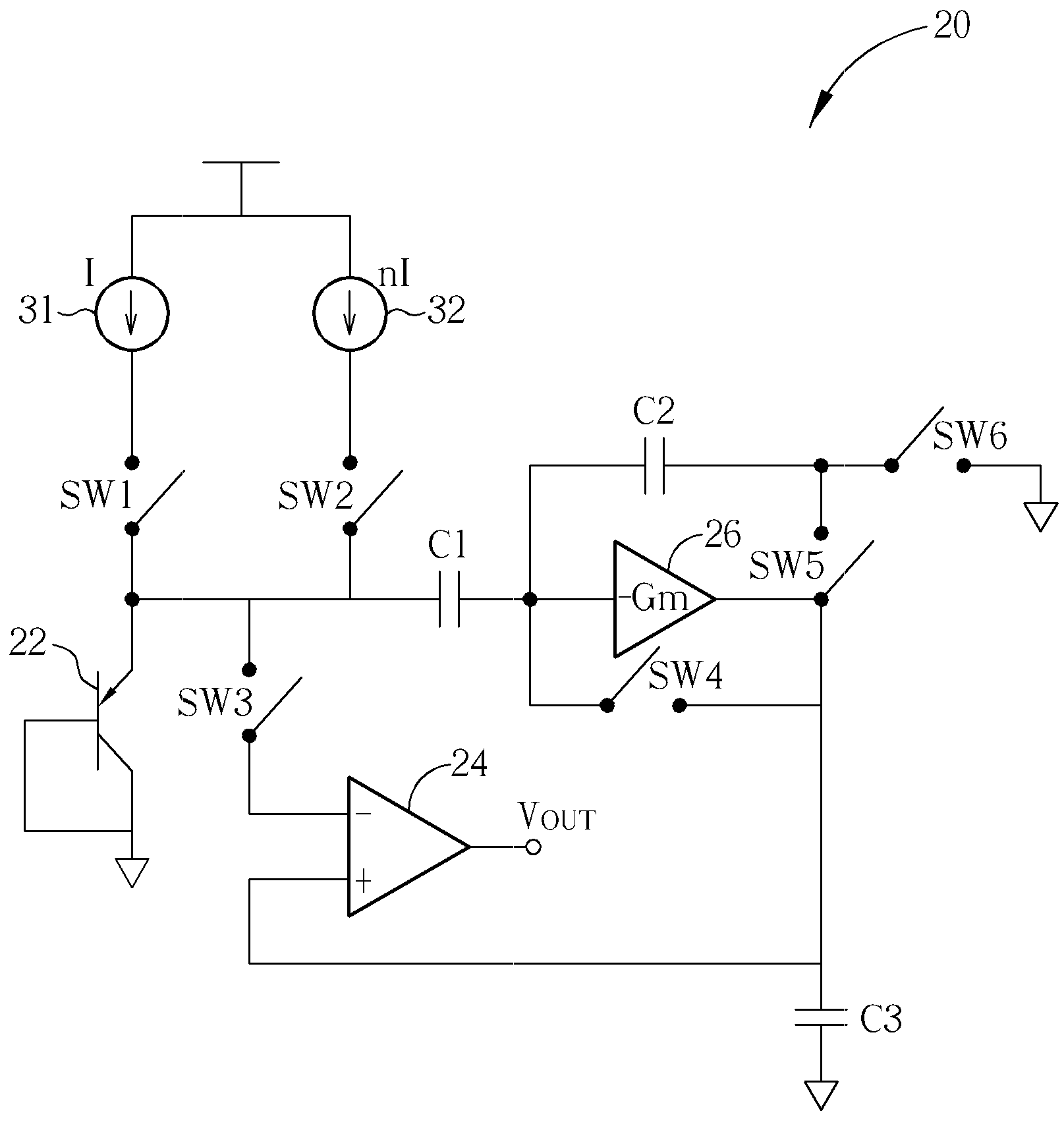
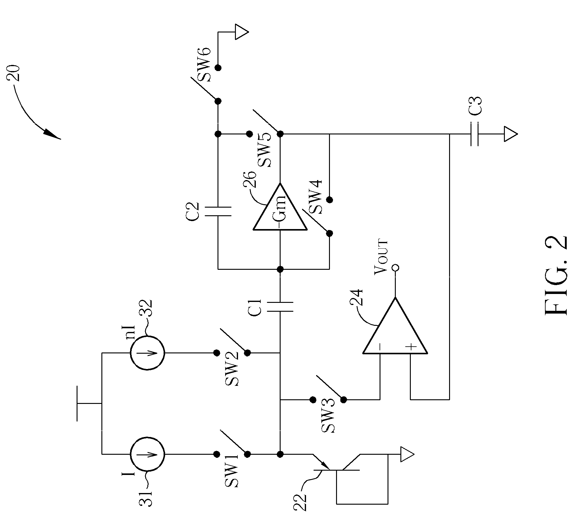
[0016]Please refer to FIG. 2. FIG. 2 is a circuitry of a temperature sensing circuit using CMOS switch-capacitor according to the present invention. The temperature sensing circuit 20 comprises a PNP bipolar junction transistor (BJT) 22, a hysteresis comparator 24, a transconductance amplifier 26, a first current source 31, a second current source 32, a first capacitor C1, a second capacitor C2, a third capacitor C3, a first switch SW1, a second switch SW2, a third switch SW3, a fourth switch SW4, a fifth switch SW5, and a sixth switch SW6. The base of the PNP BJT 22 is electrically connected to the collector of the PNP BJT 22, and the collector of the PNP BJT 22 is electrically connected to the ground. The negative input end of the hysteresis comparator 24 is electrically connected to the emitter of the PNP BJT 22 via the first switch SW1, and the positive input end of the hysteresis comparator 24 is electrically connected to the output end of the transconductance amplifier 26. The...


PUM


Abstract

A temperature sensing circuit using CMOS switch-capacitor includes a PNP BJT, a hysteresis comparator, a transconductance amplifier, two current sources, two capacitors, and six switches. A voltage complementary to the absolute temperature (CTAT) is generated according to the PNP BJT, and a voltage proportional to the absolute temperature (PTAT) is generated according to two capacitors and the transconductance amplifier. When the voltage proportional to absolute temperature is greater than the voltage complementary to absolute temperature as the temperature rising, the hysteresis comparator outputs a high level signal.

Description

BACKGROUND OF THE INVENTION[0001]1. Field of the Invention[0002]The present invention relates to a temperature sensing circuit, and more particularly, to a temperature sensing circuit using CMOS switch-capacitor.[0003]2. Description of the Prior Art[0004]In recent years, rapid developments in integrated circuit technology have reached the stage where a single-packaged chip may contain millions of transistors. As such, when an integrated circuit configured with a large number of transistors operates at a high clock rate, the amount of heat dissipated will be enormous to the extent that the operating temperature may exceed 100 degrees centigrade. Due to the change in temperature, all components in the chip will be adversely affected, since temperature and conductivity have an inversely proportional relationship. Therefore, when temperature rises, the electrical characteristics of components will change accordingly. The most evident effect is that operating speed and overall efficiency...

Claims


Application Information

Patent Timeline
IPC IPC(8): G01K7/01
CPCG01K7/01
Inventor CHEN, CHIH-CHIACHENG, LI-SHENG
Owner ADVANCED ANALOG TECH INC
Learn More