Connection and Junction Box for a Solar Module

a solar module and connection box technology, applied in the direction of contact members penetrating/cutting insulation/cable strands, coupling device connections, light radiation electric generators, etc., can solve the problems of low series connection power of solar modules, difficult mechanical charge for fixing electrical connectors, and even damage, etc., to achieve high contact reliability and long life cycle

Active Publication Date: 2010-05-06
PHOENIX CONTACT GMBH & CO KG
View PDF9 Cites 13 Cited by
  • Summary
  • Abstract
  • Description
  • Claims
  • Application Information

AI Technical Summary

Benefits of technology

[0010]Therefore, it is an object of the present invention to provide a connection and junction box for a photovoltaic solar module, which box may automatically, e.g. by means of a robot, be connected to the solar module, and offers high contact reliability and long-life cycle.

Problems solved by technology

These flexible conductor bands are very sensitive and therefore difficult to contact.
Additionally, a mechanical charge for fixing an electrical connector is also difficult because of the disk-like form of the solar module.
If a module is shaded or does not produce electricity because of a defect, this module would lower the power of the solar modules in series connection or even suffers damage without bypass diode.
It is apparent that due to the mechanical conditions, particularly the form of the solar module and the sensitiveness of the flexible flat conductor bands, a number of difficulties occur, when constructing the connection and junction box.
It is apparent that mounting such connection devices or connection boxes respectively is laborious, and is badly suited for automated mass production.
At this, it is disadvantageous that the conductor band has to be threaded into the narrow guiding arrangement, and the clamping force of the clamp arrangement may nevertheless be relatively low to be able to insert the thin conductor band into the clamp arrangement.

Method used


Image

  • Connection and Junction Box for a Solar Module
  • Connection and Junction Box for a Solar Module
  • Connection and Junction Box for a Solar Module

Examples


Embodiment Construction

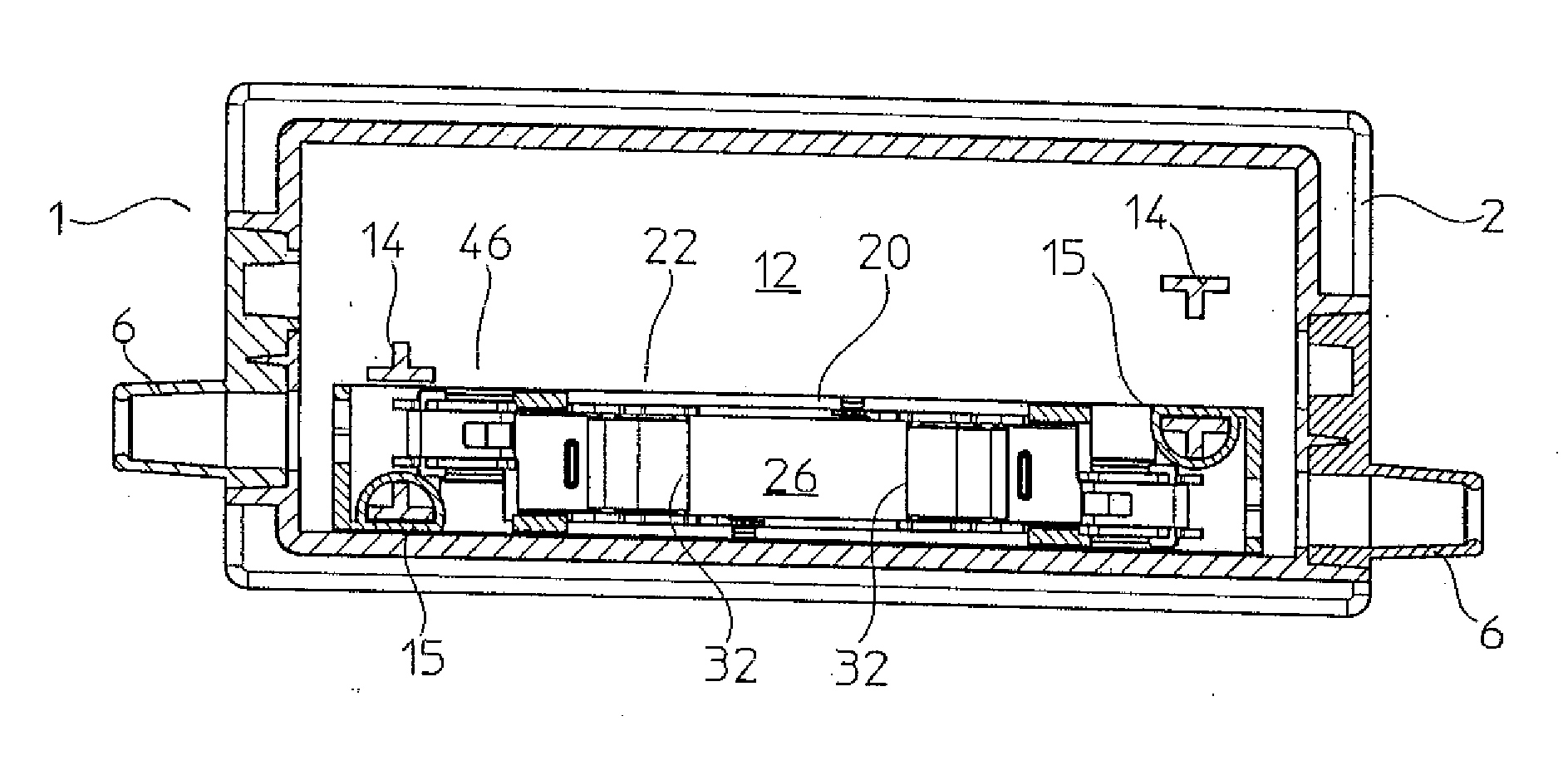
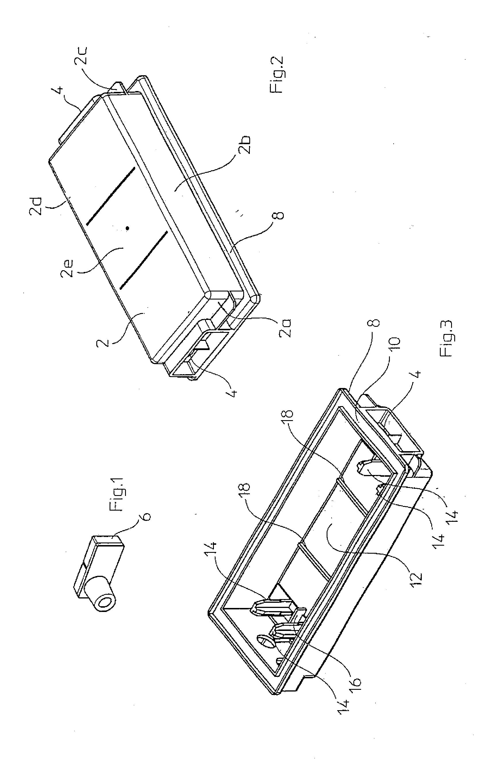
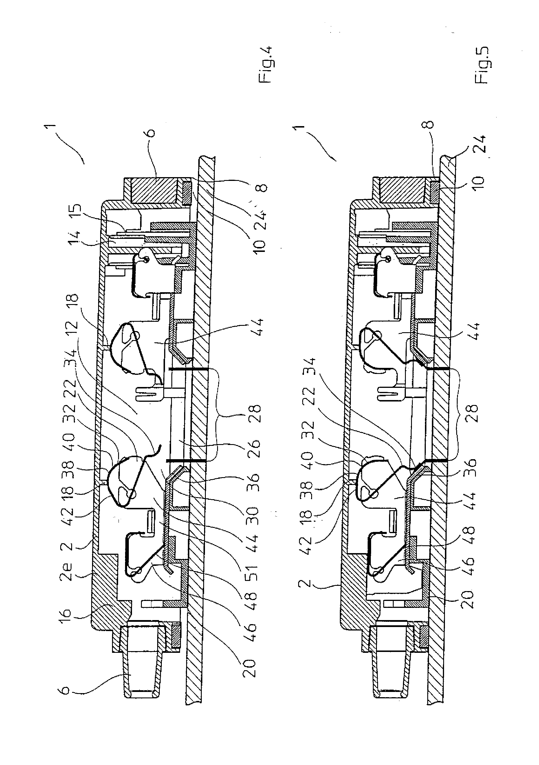
[0040]Referring to FIGS. 1-3, the connection and junction box has a housing 2 made of plastics. The housing 2 is formed by a substantially rectangular frame consisting of four side walls 2a to 2d, and a closed cap 2e connecting the four side walls and proceeding parallel to the solar module. The housing 2 being closed on five sides and being open downwards is die cast one-piece, for example. Separate bend protection grommets 6 are inserted each in connection cable lead-throughs.

[0041]Referring to FIG. 3, the housing 2 is open downwards, and has a protruding holding frame 8 with a circular glue notch 10 so that the housing 2 has a hat-like form. Finally, the connection and junction box is permanently fixed on the solar module by means of the glue placed in the glue notch 10. The hat-like or pan-like form of the housing defines an internal hollow space 12, in which the connection device not being shown in FIG. 3 is substantially waterproof housed in mounting state.

[0042]Alignment pins...


PUM


Abstract

A connection and junction box for a photovoltaic solar module having flexible flat conductor band protruding from the surface of the solar module, wherein the connection and junction box has an insertion mouth at its side facing the solar module in mounted state, for at least one flexible flat conductor band of the solar module, and comprises a housing for attaching on the solar module, and a connection device for the flexible flat conductor band, positioned in the housing, the connection device has an electrical contact clamp, which is closed when putting the box on the solar module, and thereby catches and contacts the flat conductor band.

Description

FIELD OF THE INVENTION[0001]The invention relates to a connection and junction box for a photovoltaic solar module having flexible flat conductor bands protruding from the surface of the solar module, as well as to a connection device for the connection and junction box.BACKGROUND OF THE INVENTION[0002]Over the past years, producing photovoltaic solar modules has literally been booming, inter alia due to the increased demand on environmentally sound energy production. The direct conversion of sunlight into electric current by means of photovoltaic solar modules is entirely emission-free, and no risks for humans and the environment are almost involved. For example, complete roofs of new buildings are therefore recently overlaid with solar modules, and even “solar power plants” are built. Due to the technical development of photovoltaics, using solar modules more and more becomes efficient even in more unfavourable latitudes such as Middle Europe and Northern America so that especiall...

Claims


Application Information

Patent Timeline
Patent Type & Authority Applications(United States)
IPC IPC(8): H02N6/00
CPCH01R4/4809H01R12/592H02S40/34H01R4/489Y02E10/50H01R9/2416H01L31/02013
Inventor GIEFERS, STEFAN
Owner PHOENIX CONTACT GMBH & CO KG
Why Eureka
Try Eureka