Walking assistance device

a technology of assistance device and walking aid, which is applied in the field of walking assistance device, can solve the problems of poor durability, low rotational accuracy, and screw inevitably having a long stroke, and achieve the effects of reducing the diameter of the actuator, facilitating movement, and facilitating movemen

Active Publication Date: 2010-05-06
HONDA MOTOR CO LTD
View PDF5 Cites 21 Cited by
  • Summary
  • Abstract
  • Description
  • Claims
  • Application Information

AI Technical Summary

Benefits of technology

[0017]This arrangement allows the linear-motion actuator to be simplified, smaller in diameter, and lighter-weight, as compared with

Problems solved by technology

However, the walking assistance equipment disclosed in patent document 1 has been posing a problem of poor durability, low rotational accuracy, delayed following attributable to the flexible joint used with the drive mechanism.
There has

Method used


Image

  • Walking assistance device
  • Walking assistance device
  • Walking assistance device

Examples


Embodiment Construction

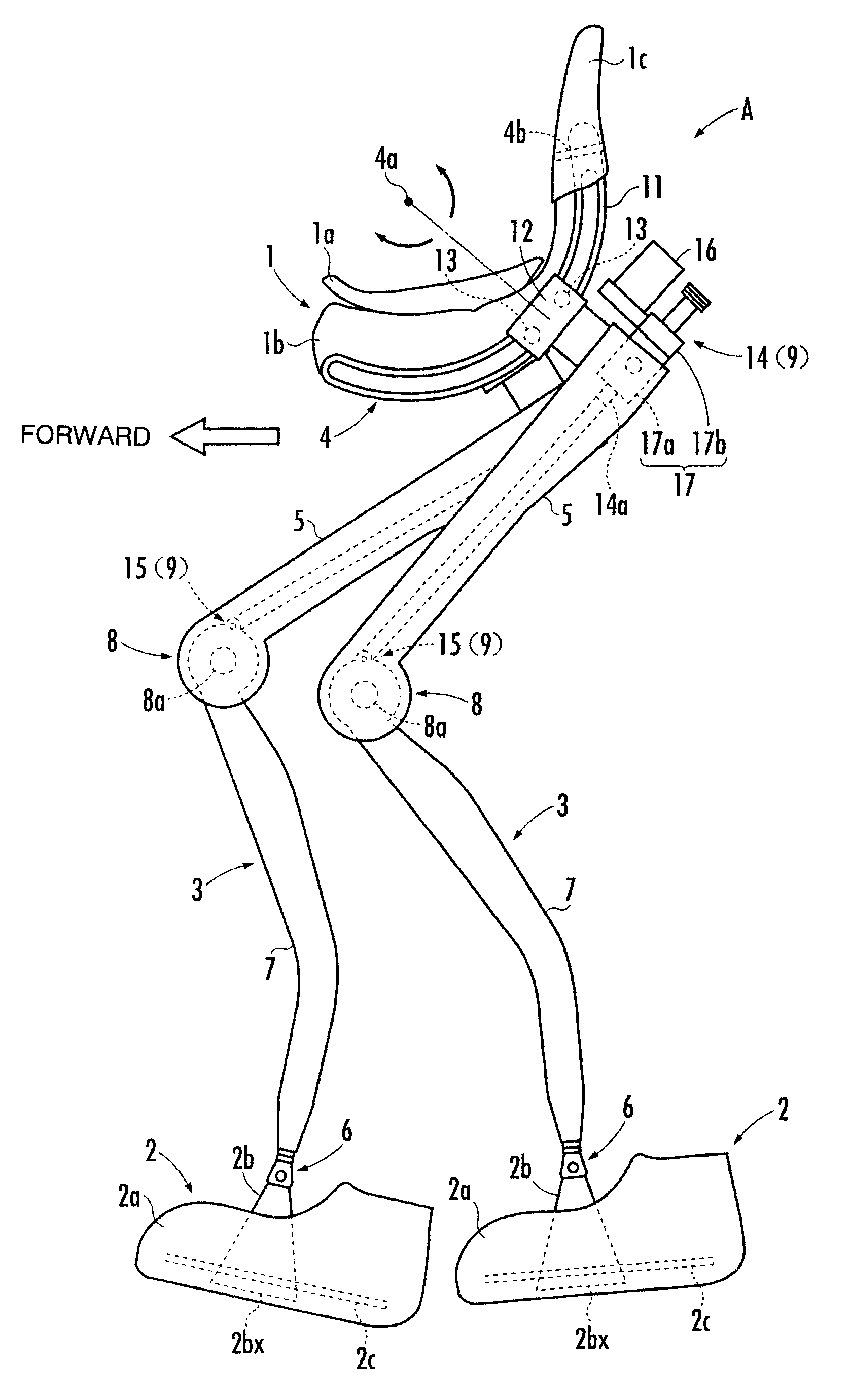
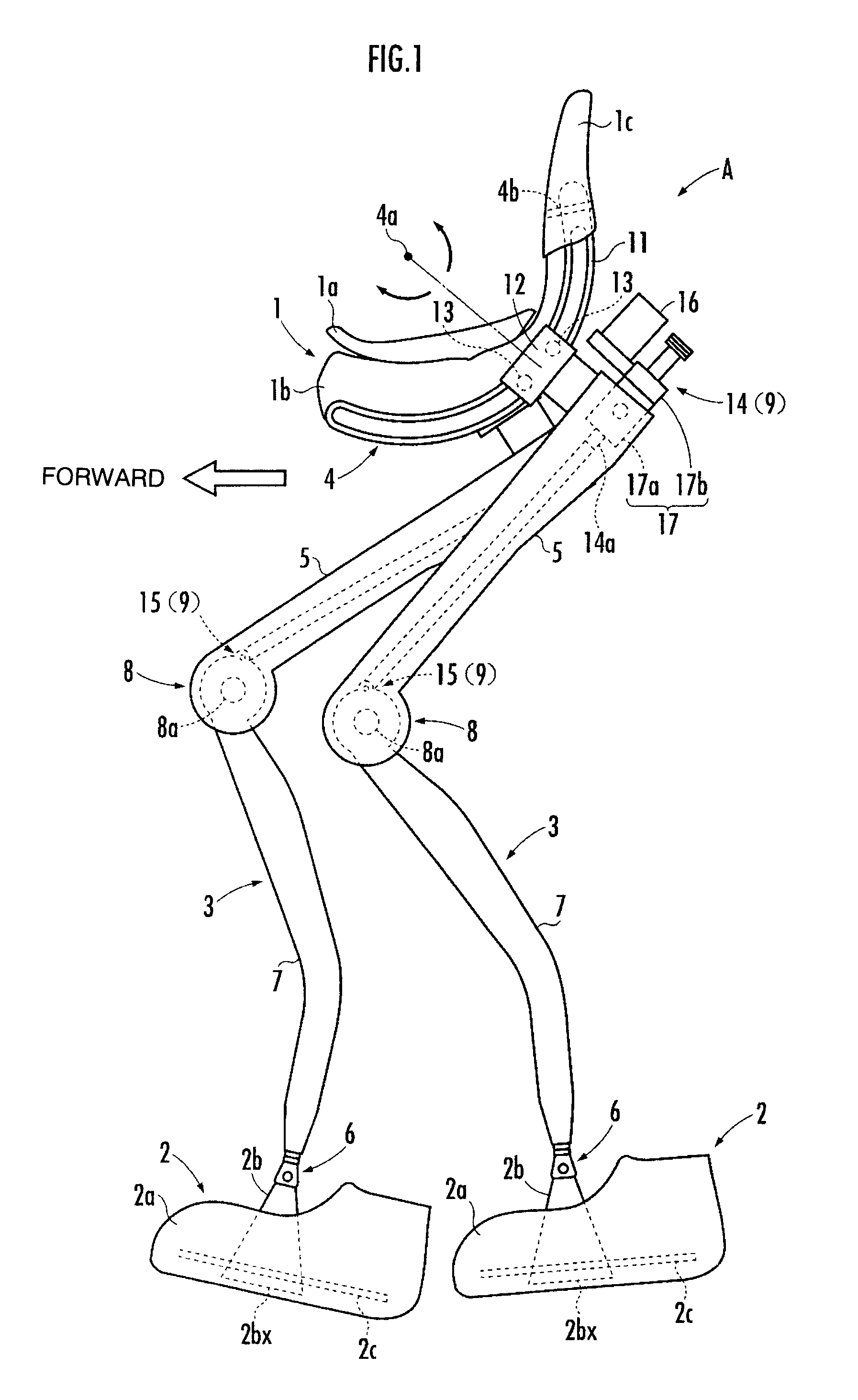
[0022]The following will describe a walking assistance device A according to an embodiment of the present invention with reference to the accompanying drawings.

[0023]As illustrated in FIG. 1, the walking assistance device A is provided with a seating assembly 1 serving as a load transmit assembly, a pair of right and left foot-worn assemblies 2 and 2 to be attached to the feet of individual legs of a user (not shown), and a pair of right and left leg links 3 and 3 which connect the foot-worn assemblies 2 and 2, respectively, to the seating assembly 1. The right and left foot-worn assemblies are laterally symmetrical to each other and share the same structure. The right and left leg links 3 and 3 are also laterally symmetrical to each other and share the same structure. In the description of the present embodiment, the lateral direction of the walking assistance device A means the lateral direction of the user having the foot-worn assemblies 2 and 2 attached to his or her feet (the d...


PUM


Abstract

A walking assistance device has a drive mechanism, which is provided with a linear-motion actuator including an electric motor installed in the upper link member, nut members which are rotationally driven by the electric motor, and a linear-motion output shaft which linearly moves in the direction of the axial centers of the nut members, and a crank arm which is secured to the lower link member coaxially with a joint axis of a third joint and swingably attached to one end of the linear-motion output shaft. The drive mechanism is constructed such that a translational force output from the linear-motion output shaft of the linear-motion actuator is converted into a rotational driving force of the third joint through the crank arm.

Description

BACKGROUND OF THE INVENTION[0001]1. Field of the Invention[0002]The present invention relates to a walking assistance device which assists a user (person) with walking.[0003]2. Description of the Related Art[0004]Hitherto, as this type of walking assistance device, Japanese Patent Application Laid-Open No. 2002-191654 (hereinafter referred to as “patent document 1”), for example, discloses walking assistance equipment constituted of a thigh attachable member to be attached to a thigh and a crus attachable member which is rotatably installed to the thigh attachable member and which is to be attached to a crus. The walking assistance equipment has a drive mechanism comprised of a motor installed to the thigh attachable member, a socket installed to the crus attachable member, a ball screw threaded in a screw hole of the socket, and a flexible joint connecting a motor shaft and the ball screw. The ball screw moves into or out of the socket to change the distance between the bottom end ...

Claims


Application Information

Patent Timeline
IPC IPC(8): A61H3/00A61F2/48
CPCA61H3/008A61H2201/1633A61H2201/5061A61H3/00A61H2201/1215A61H2201/1623A61H2201/1642A61H2201/165A61H2201/1676A61H2201/5069A61H2201/149
Inventor MATSUOKA, YOSHIHISAHIKI, YUTAKA
Owner HONDA MOTOR CO LTD
Why Eureka
Try Eureka