Intramedullary locked compression screw for stabilization and union of complex ankle and subtalar deformities

a technology of intramedullary locking and compression screw, which is applied in the field of intramedullary locking compression screw for stabilizing and union of complex ankle and subtalar deformities, can solve the problems of defective cartilage in the ankle, complex joint of the ankle, and a lot of stress and pounding

Inactive Publication Date: 2010-05-06
MANDERSON EASTON L
View PDF12 Cites 39 Cited by
  • Summary
  • Abstract
  • Description
  • Claims
  • Application Information

AI Technical Summary

Benefits of technology

[0023]provide an implant that can endure the stress and strain of early...

Problems solved by technology

The ankle is a complex joint that, because of its position and its role in walking, takes a lot of stress and pounding.
Defective cartilage in an ankle, either as a result of injury to or from degeneration of the ankle, is often a painful condition.
But, this method is not without its problems.
The requirement to locate the locking screws in the nails is a very difficult process for some surgeons.
This difficulty in using intramedullary nails is unfortunate because the use of intramedullary nails allows the patient t...

Method used


Image

  • Intramedullary locked compression screw for stabilization and union of complex ankle and subtalar deformities
  • Intramedullary locked compression screw for stabilization and union of complex ankle and subtalar deformities
  • Intramedullary locked compression screw for stabilization and union of complex ankle and subtalar deformities

Examples


Embodiment Construction

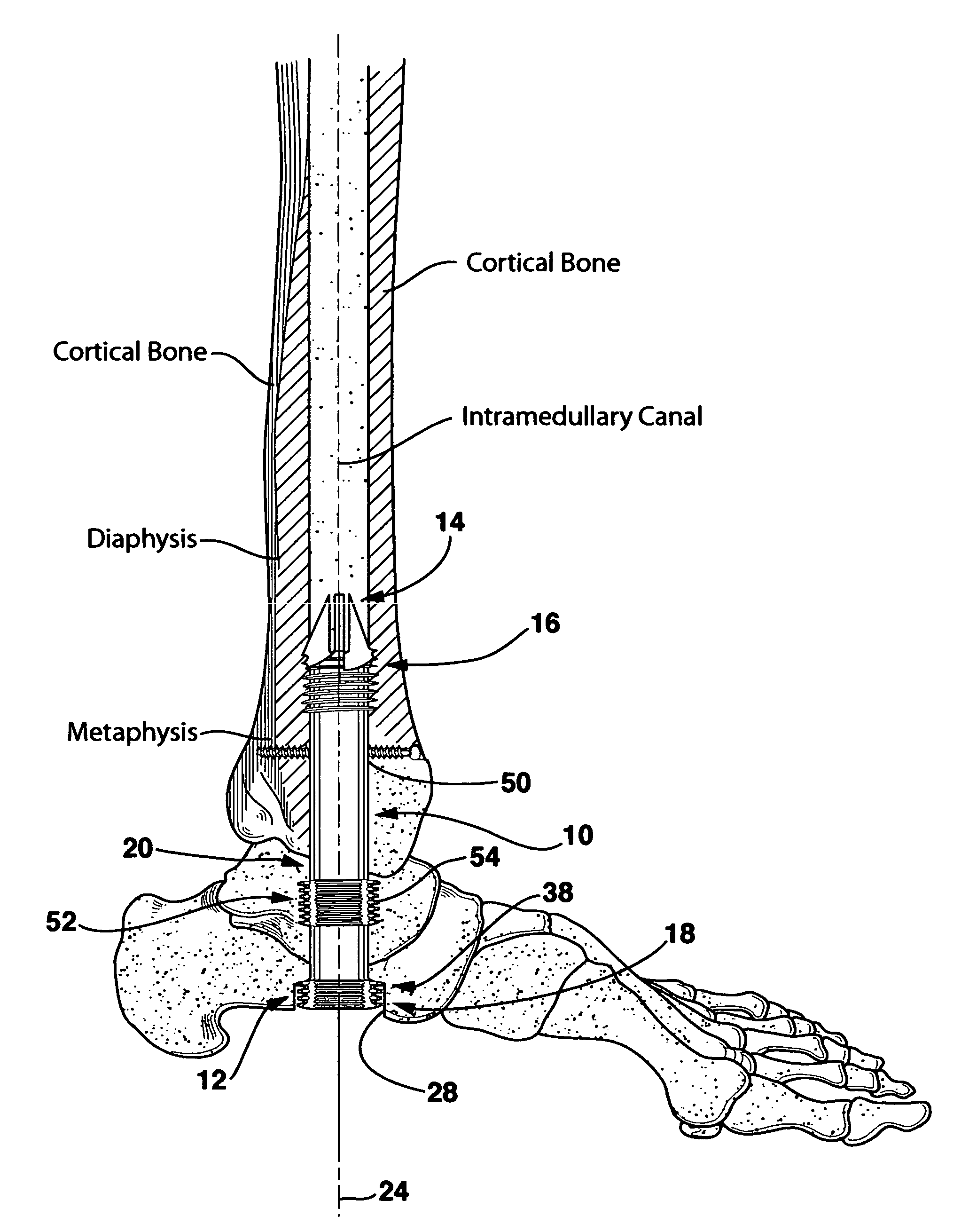
[0039]In order that the invention may be clearly understood and readily carried into effect, preferred embodiments of the invention will now be described, by way of example only and not to limit the invention, with reference to the accompanying drawings. The intramedullary ankle fusion device of the present invention is shown in the drawings generally labeled 10.

[0040]The ankle fusion device 10 is a preferred embodiment shown in FIGS. 3-8 is a double threaded cannula having a proximal end 12, an opposite distal end 14, a tibial component 16 at the distal end 14, a calcaneus component 18 at the proximal end 12 and a midsection 20 extending between the tibial component 16 and the calcaneus component 18.

[0041]Because the ankle fusion device 10 is a cannula, the ankle fusion device 10 has a lumen 22 (FIG. 5 and shown in phantom in FIGS. 4 and 10) extending along a midline 24 of the ankle fusion device 10 from the proximal end 12 to the distal end 14.

[0042]The tibial component 16 include...


PUM


Abstract

An implant for causing fusion of bones in an ankle is disclosed. The implant, in a preferred embodiment, is a cannulated screw with threads at the leading end and threads at the trailing end having a a tibial component that interacts with the tibia, a calcaneus component that interacts with the calcaneus and a midsection extending between the tibial component and the calcaneus component. The implant is placed in a borehole formed in the tibia, talus and calcaneus and causes the tibia and talus to be moved into compressive contact with each other. As a result, the ends of the tibia and talus that have previously had the cartilage removed down to bloody bone are coapted together to allow fusion. In another embodiment of the invention, a middle threaded portion is placed between the tibial component and the calcaneus component. The middle threaded portion interacts with the talus to help add compressive force to the fusion process. The invention also includes a method for using the implant to fuse the bones of the ankle together. The method includes steps of producing an implant and then using the implant to apply compressive forces on the bones of the ankle. The invention in one embodiment also includes a method that uses images such as x-ray images preoperatively to determine the length and width of the disclosed implant or any other implant with each patient's unique anatomy will properly allow coaption of the ends of the prepared tibia and talus at the ankle joint. The implant is inserted from the bottom of the foot through a predetermined hole in the calcaneus which extends through the talus into the diaphysis of the tibia. When properly inserted and seated in the bones, the implant is locked by screws.

Description

BACKGROUND OF THE INVENTION[0001]1. Field of the Invention[0002]The present invention relates generally to methods and medical devices that fuse bones in an ankle joint and more particularly to methods and medical devices for fusing bones in a painful ankle joint to relieve pain in the joint.[0003]2. Description of Related Art[0004]The ankle is a complex joint that, because of its position and its role in walking, takes a lot of stress and pounding. A typical human takes about one million steps a year and the stress of each step is transmitted through the respective ankle of the foot. What is commonly referred to as the ankle is actually two joints, the subtalar joint and the true ankle joint. The ends of the bones in these joints are covered by articular cartilage.[0005]As shown in FIGS. 1 and 2, the true ankle joint is composed of three bones: the tibia, the fibula and talus. As seen from a back, or posterior, view (FIG. 2), the tibia forms the inside, or medial, portion of the an...

Claims


Application Information

Patent Timeline
IPC IPC(8): A61F2/28A61B17/04
CPCA61B17/7225A61B17/7233A61B17/7291A61B17/863A61F2/4202A61F2002/30224A61F2002/30622A61F2002/30859A61F2230/0069
Inventor MANDERSON, EASTON L.
Owner MANDERSON EASTON L
Why Eureka
Try Eureka