Methods and systems for gas turbine syngas warm-up with low emissions

a gas turbine and warm-up technology, applied in the field of gas turbine syngas warm-up with low emissions, can solve the problems of visible flares and higher emissions for an extended time period

Active Publication Date: 2010-05-13
AIR PROD & CHEM INC
View PDF10 Cites 16 Cited by
  • Summary
  • Abstract
  • Description
  • Claims
  • Application Information

AI Technical Summary

Problems solved by technology

However, using the existing warm-up line between the syngas stop and control valves to channel heated syngas to flare while meeting GT syngas temp

Method used


Image

  • Methods and systems for gas turbine syngas warm-up with low emissions
  • Methods and systems for gas turbine syngas warm-up with low emissions
  • Methods and systems for gas turbine syngas warm-up with low emissions

Examples


Embodiment Construction

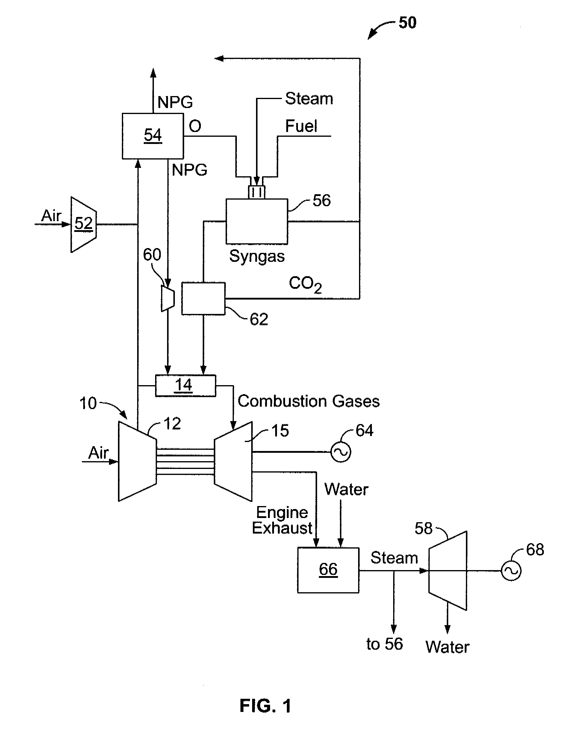
[0008]FIG. 1 is a schematic diagram of a portion of an exemplary integrated gasification combined-cycle (IGCC) power generation system 50. IGCC system 50 generally includes a main air compressor 52, an air separation unit 54 coupled in flow communication to compressor 52, a gasifier 56 coupled in flow communication to air separation unit 54, a gas turbine engine 10, coupled in flow communication to gasifier 56, and a steam turbine 58. In operation, compressor 52 compresses ambient air. The compressed air is channeled to air separation unit 54. In some embodiments, in addition or alternative to compressor 52, compressed air from gas turbine engine compressor 12 is supplied to air separation unit 54. Air separation unit 54 uses the compressed air to generate oxygen for use by gasifier 56. More specifically, air separation unit 54 separates the compressed air into separate flows of oxygen and a gas by-product, sometimes referred to as a “process gas.” The process gas generated by air s...


PUM


Abstract

Methods and systems of operating an integrated gasification combined cycle system are provided. The method includes coupling a non-fuel fluid conduit to a fuel conduit, warming a flow of non-fuel fluid, and channeling the warmed non-fuel fluid through the fuel conduit such that heat from the warmed non-fuel fluid heats the fuel conduit to a predetermined temperature.

Description

BACKGROUND OF THE INVENTION[0001]This invention relates generally to integrated gasification combined cycle (IGCC) systems, and more specifically to methods and systems for facilitating reduced flaring during startup of the system.[0002]At least some known IGCC systems startup on a fuel such as natural gas to provide heat to various subsystems and to warm-up components of the IGCC system such that operational temperature limits are not exceeded during startup or conversion to operation using syngas fuel. For example, a saturator generally includes an operating requirement of being pre-warmed during startup and preventing boiling of the circulation loop. For protection of internal gas turbine components, the syngas supplied to the gas turbine typically is required to be superheated to a final temperature in the range of approximately 250 degrees Celsius. Additionally, diluent nitrogen is heated with extraction air and vent to atmosphere. Currently, such temperature requirements are m...

Claims


Application Information

Patent Timeline
IPC IPC(8): F02C6/18F02C6/00
CPCF02C6/18F02C7/224Y02E20/18
Inventor RUSS, FREDRIC S.HOLLAND, DOUGLAS K.VILLA, CHRISTOPHER J.KASSMAN, JERROLD S.NGUYEN, EILEEN T.PRATER, MATTHEW C.
Owner AIR PROD & CHEM INC
Why Eureka
Try Eureka