Coriolis gyro

a technology of coriolis and gyros, applied in the field of coriolis gyros, can solve the problems of quadrature compensation, i.e., virtually impossible “balancing-out” of the structure by an actuating element, and requires complex manufacturing processes. , to achieve the effect of reducing the sensitivity to acceleration and vibration

Active Publication Date: 2010-05-13
NORSROP GRUMAN LITEF GMBKH
View PDF14 Cites 77 Cited by
  • Summary
  • Abstract
  • Description
  • Claims
  • Application Information

AI Technical Summary

Benefits of technology

[0008]It is therefore the object of the invention to provide a rotation rate sensor based on spring and mass systems, having reduced sensitivity to accelerations and vibration.

Problems solved by technology

Disadvantages: Most known structures require soft suspension (e. g. ring, bar; an exception is the so-called HRG (Hemispherical Resonator Gyroscope), which requires complex manufacturing processes due to its “true three-dimensional” form).
Such structures are deflected relatively significantly when accelerations and vibration occur, leading to errors in many force transmitters (e.g. electrostatic force transmitters) and taps (e.g. capacitive taps).
Also, quadrature compensation, i.e. “balancing-out” of the structure by an actuating element, is virtually impossible, since the required forces are too great.
Disadvantages: Vibration and, frequently, linear accelerations can excite one or both useful modes and therefore cause error signals.

Method used


Image

  • Coriolis gyro
  • Coriolis gyro
  • Coriolis gyro

Examples


first embodiment

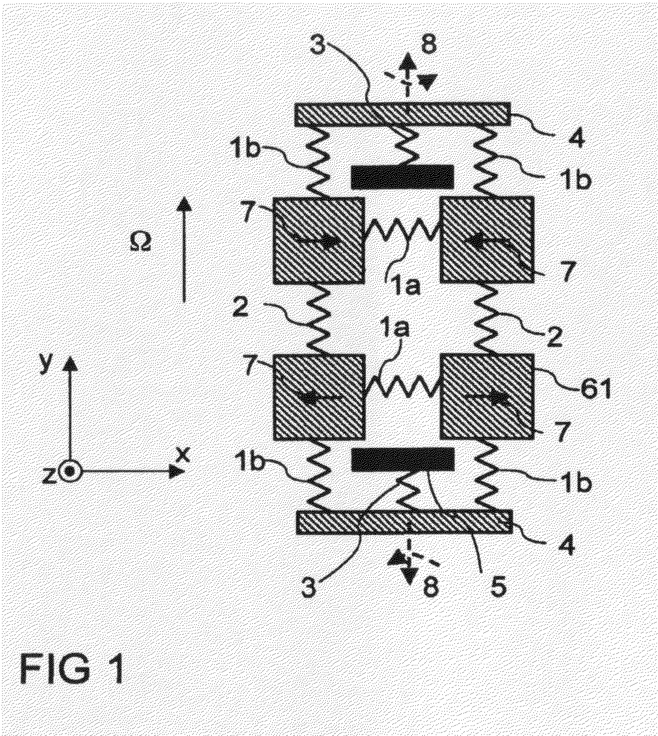
[0025]FIG. 1 is a mechanical schematic diagram of a Coriolis gyro based on a spring and mass system, in a first embodiment, having four first mass elements 61 coupled via first x coupling spring elements 1a and coupling spring elements 2 to one another. The described elements are coupled via second x coupling spring elements 1b, connecting elements 4 and first substrate spring elements 3 to a substrate 5 (shown in FIG. 1 by means of an anchor). Two coupled out-of-phase linear oscillations of the mass elements 61, again out-of-phase with respect to one another, serve as the excitation mode 7. When the Coriolis gyro is rotated about a sensitive axis Ω, a detection mode 8 is excited (represented as two coupled out-of-phase rotary oscillations about a y axis parallel to the sensitive axis Ω and at right angles to the x direction (Lin-Rot)). The x coupling spring elements 1a, 1b are soft in the x direction, and otherwise stiff. The coupling spring elements 2 may be isotropically soft (i....

second embodiment

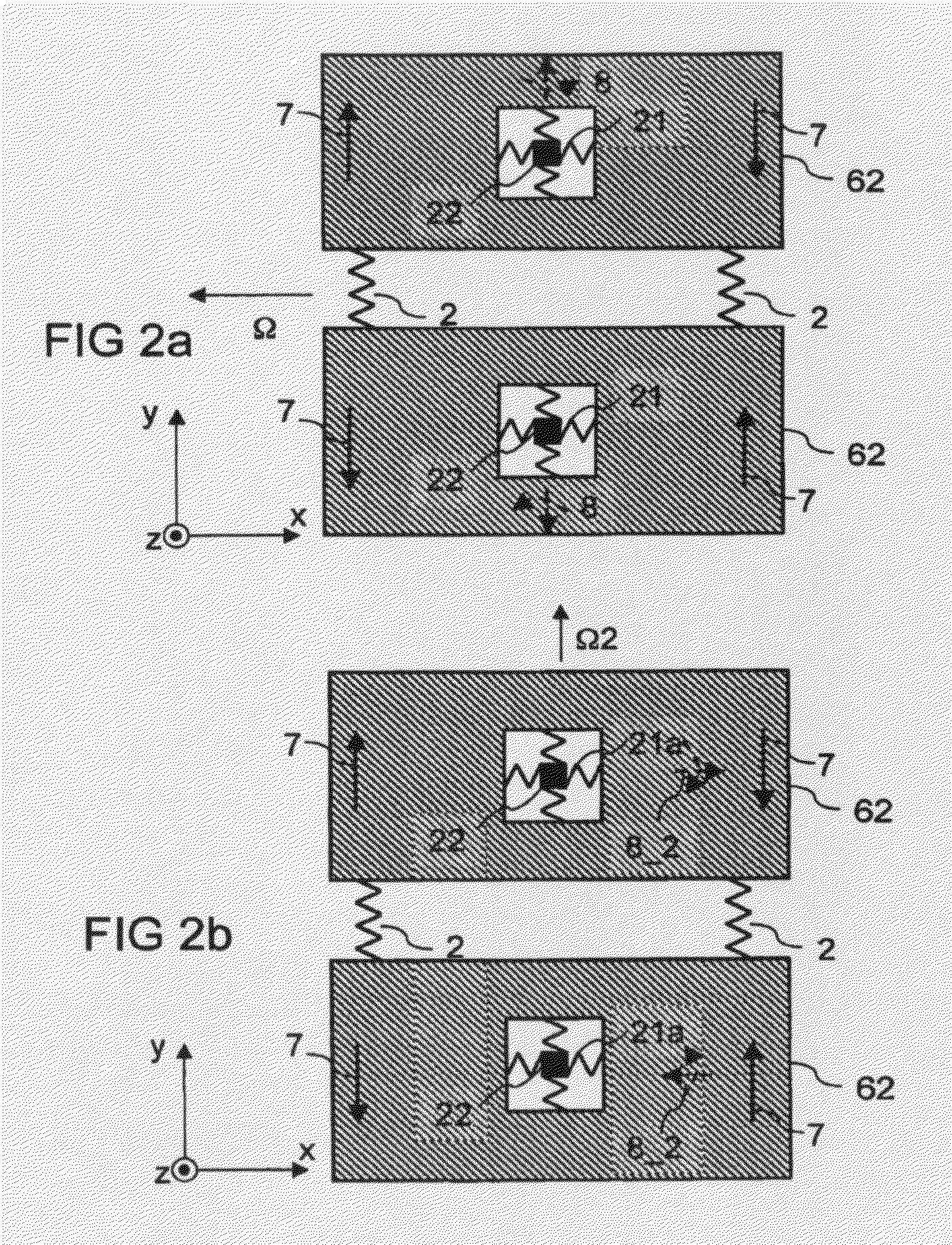
[0026]FIG. 2a is a schematic diagram of a Coriolis gyro based on a spring and mass system in a In this embodiment, two second mass elements 62 are coupled by coupling spring elements 2 to one another and are coupled via second substrate spring elements 21 to a substrate 5 (illustrated by an anchor 22). Two coupled out-of-phase rotary oscillations of the mass elements 62 about the substrate anchor 22, about a z direction, serve as the excitation mode 7. During rotation of the Coriolis gyro about its sensitive axis Ω, two coupled out-of-phase rotary oscillations about a y axis are excited (Rot-Rot) as the detection mode, and are at right angles to the sensitive axis Ω and to the rotation axis z of the excitation mode 7. The second substrate spring elements 21 are soft during rotation about the z and y axes, but are otherwise as stiff as possible. The coupling spring elements 2 may be isotropically soft (i.e. soft for all loads). In the case of this Coriolis gyro the useful modes (i.e...

third embodiment

[0028]FIG. 3 is a schematic diagram of a Coriolis gyro based on a spring and mass system. Four third mass elements 63 are coupled via xy coupling spring elements 23 to one another and to a substrate 5 (illustrated by an anchor 24). Linear oscillations of the mass elements 63 at 45° to the x and y directions are used as the excitation mode 7. In this case, two obliquely opposed third mass elements 63 each move towards one another when the respective other two opposed third mass elements 63 move away from one another. During rotation of the Coriolis gyro about the sensitive axis Ω (at right angles to the x and y directions and therefore parallel to the z direction), a linear oscillation is excited as the detection mode, and is shifted with respect to the excitation mode (Lin-Lin). In this case, the third mass elements 63, which are adjacent in the x direction, move towards one another in the x direction when third mass elements 63, adjacent in the y direction, are moving away from one...


PUM


Abstract

A Coriolis gyro having an arrangement which comprises a substrate, at least two individual structures and spring elements. The spring elements couple the individual structures to the substrate and to one another. Force transmitters and taps are provided. The arrangement has at least one excitation mode which can be excited by the force transmitters and at least one detection mode which can be measured by the taps. The excitation mode and the detection mode are closed, as a result of which no disturbance excitations of the excitation mode and of the detection mode can be caused by linear accelerations and / or vibrations if there is no need to take account of manufacturing tolerances.

Description

BACKGROUND[0001]1. Field of the Invention[0002]The present invention relates to Coriolis gyros.[0003]2. Description of the Prior Art[0004]Coriolis gyros (coriolis vibrating gyroscopes) fall within two classes, each corresponding to the oscillation mode utilized. The two classes are: (1) shape and bending oscillations (e.g. wine glass (HRG: “Hemispherical Resonator Gyroscope”), ring, bar); and (2) spring and mass system (e.g. Lin-Rot, Rot-Rot, Lin-Lin, wherein Lin-Rot means that the excitation mode contains linear movements (“Lin”) and the detection mode contains rotary movements (“Rot”). Rot-Rot and Lin-Lin are defined correspondingly.)[0005]Such classes of Coriolis gyros have specific advantages and disadvantages with respect to vibration and acceleration sensitivity. The relative advantages and disadvantages of the two classes are discussed below.[0006]1. Shape and Bending OscillationsAdvantages: Externally closed useful modes (excitation and detection mode) are typical, i.e. such...

Claims


Application Information

Patent Timeline
Patent Type & Authority Applications(United States)
IPC IPC(8): G01C19/56
CPCG01C19/574
Inventor WOLFRAM, GEIGER
Owner NORSROP GRUMAN LITEF GMBKH
Why Eureka
Try Eureka