Control system for internal combustion engine

a control system and internal combustion engine technology, applied in the direction of electric control, machines/engines, mechanical apparatus, etc., can solve the problems of increasing manufacturing costs, affecting the design of phase compensators, and affecting the performance of the engine, so as to reduce the delay of detecting components indicative of changes in engine output torque, reduce the effect of suppressing vibration of the vehicle powertrain, and reduce the delay of detecting components indicative of engine output torqu

Inactive Publication Date: 2010-05-13
HONDA MOTOR CO LTD
View PDF14 Cites 9 Cited by
  • Summary
  • Abstract
  • Description
  • Claims
  • Application Information

AI Technical Summary

Benefits of technology

[0036]With this configuration, the feedforward correction amount is generated during the correction period which is substantially equal to the resonance period of the vehicle powertrain from the time when the rapid change in the demand torque of the engine is detected; the high-pass filtering of the detected engine rotational speed is performed; the first output torque control amount of the engine is corrected with the feedforward correction amount; and the second output torque control amount of the engine is corrected in the feedback manner according to the high-pass filtered engine rotational speed. Therefore, the vibration of the vehicle powertrain can be effectively suppressed while the output torque changing characteristic of the engine is maintained at the almost same level. Further, a negative effect, such that the vibration is conversely enlarged due to too long period of performing the feedforward correction, is not caused. Further, the delay of detecting the component indicative of changes in the engine output torque can be reduced greatly. Consequently, the effect of suppressing vibration of the vehicle powertrain can be improved.

Problems solved by technology

Accordingly, an amount of calculations in the control device is great.
Therefore, it is necessary to use a high-performance processing unit for coping with a state where the accelerator opening rapidly changes and the vibration suppression control is required, which causes a rise in the manufacturing cost.
Further, according to the device shown in the patent document 1, there is another problem that the man power for designing the phase compensator becomes great.
Further, in the device shown in the patent document 2, the effect of suppressing the vibration may not be sufficiently obtained due to a detection delay and a calculation delay of the derivative acceleration DA.
Further, since the influence of the detection delay or the calculation delay changes depending on the rotational speed of the engine, it is difficult to obtain a good effect of suppressing the vibration in all engine operating conditions.

Method used


Image

  • Control system for internal combustion engine
  • Control system for internal combustion engine
  • Control system for internal combustion engine

Examples


Embodiment Construction

[0061]Preferred embodiments of the present invention will now be described with reference to the drawings.

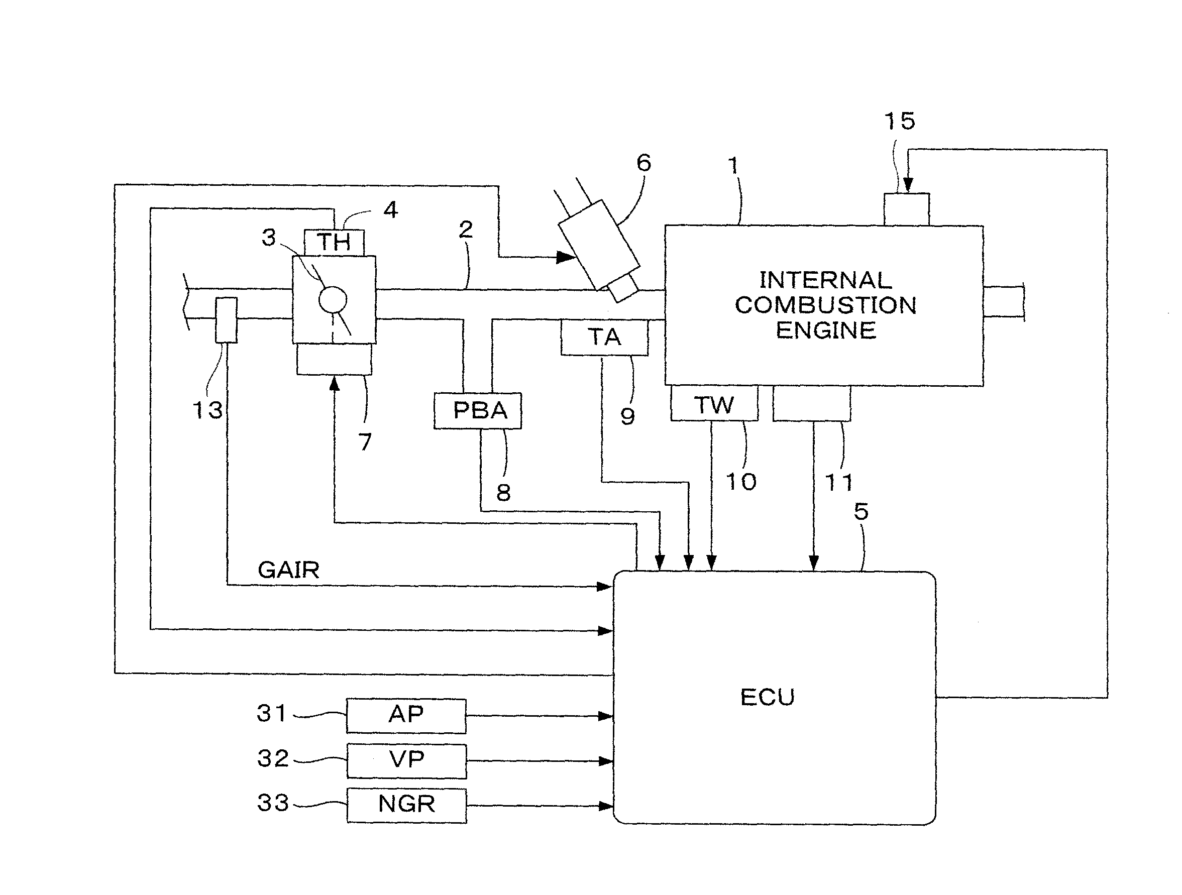
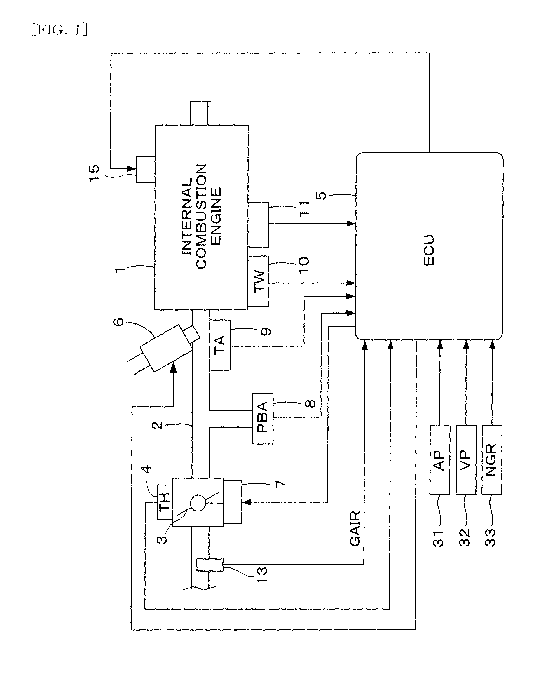
[0062]FIG. 1 is a schematic diagram showing a configuration of an internal combustion engine and a control system therefor according to one embodiment of the present invention. In FIG. 1, the internal combustion engine 1 (hereinafter referred to as “engine”) for example, has 4 cylinders, and has an intake pipe 2 provided with a throttle valve 3. A throttle valve opening (TH) sensor 4 is connected to the throttle valve 3, so as to output an electrical signal corresponding to an opening of the throttle valve 3 and supply the electrical signal to an electronic control unit (hereinafter referred to as (ECU)) 5. An actuator 7 for actuating the throttle valve 3 is connected to the throttle valve 3, and the operation of the actuator 7 is controlled by the ECU 5.

[0063]An intake air flow rate sensor 13 for detecting an intake air flow rate GAIR of the engine 1 is disposed in the intake p...


PUM


Abstract

A control system for an internal combustion engine for driving a vehicle, which controls an output torque of the engine, is provided. In this control system, a rapid change in a demand torque of the engine is detected, and a feedforward correction amount is generated during a correction period which is substantially equal to a resonance period of a powertrain of the vehicle, from a time when the rapid change in the demand torque is detected. An output torque control amount of the engine is corrected with the feedforward correction amount. A torque change amount integrated value is calculated by integrating an amount of change in the demand torque, and the feedforward correction amount is generated according to the torque change amount integrated value.

Description

TECHNICAL FIELD[0001]The present invention relates to a control system for an internal combustion engine which drives a vehicle, and particularly to a control system which suppresses vibration of the vehicle caused by changes in the output torque of the internal combustion engine.BACKGROUND ART[0002]The patent document 1 described below discloses a throttle control device which controls an opening of the throttle valve so as to suppress vibration of a vehicle powertrain generated upon operation of the accelerator pedal. According to this device, an inverse filter control for suppressing the vibration of the powertrain and another control (e.g., a retard control of the ignition timing) for suppressing the vibration are performed so as not to interfere with each other. The inverse filter control is a control in which a throttle valve opening command value is calculated from an accelerator opening using a phase compensator having a transfer characteristic of W (=Gm / Gp), wherein Gp is a...

Claims


Application Information

Patent Timeline
Patent Type & Authority Applications(United States)
IPC IPC(8): F02D11/10F02M7/00
CPCF02D11/105F02D41/10F02D41/1498F02D2041/141F02D2250/21
Inventor SHIKAMA, MAHITOKOHNO, RYUJIYAMAZAKI, EISEIHIRONOBU, HIDEKAZU
Owner HONDA MOTOR CO LTD
Why Eureka
Try Eureka