Pixelated photovoltaic array method and apparatus

Inactive Publication Date: 2010-05-13
HRL LAB
View PDF9 Cites 15 Cited by
  • Summary
  • Abstract
  • Description
  • Claims
  • Application Information

AI Technical Summary

Benefits of technology

[0026]It will be appreciated by a skilled artisan that high device efficiencies are possible by practicing the methods taught herein. In preferred

Problems solved by technology

Solar light also has certain disadvantages, including a broad spectrum of wavelengths that can lead to limited efficiencies, and the lack of availability at night.
Previously, these measurements had required large and expensive transformers filled with oil or gas to isolate the sensor from ground potential.
Because illumination of the metal occurs, some of the incident light is lost to reflection and absorption by the metal contact.
The lateral current in the surface layer creates a non-uniform surface potential and can lead to significant ohmic losses due to the relatively low conductivity of the surface layer.
While ohmic losses can be reduced by increasing the thickness and doping density of the emitter layer, a thick, heavily doped emitter layer is undes

Method used


Image

  • Pixelated photovoltaic array method and apparatus
  • Pixelated photovoltaic array method and apparatus
  • Pixelated photovoltaic array method and apparatus

Examples


Embodiment Construction

[0030]The apparatus and methods of the present invention will now be described in detail by reference to various non-limiting embodiments of the invention.

[0031]Unless otherwise indicated, all numbers expressing dimensions, compositions, efficiencies, and so forth used in the specification and claims are to be understood as being modified in all instances by the term “about.” Without limiting the application of the doctrine of equivalents to the scope of the claims, each numerical parameter should at least be construed in light of the number of reported significant digits and by applying ordinary rounding techniques.

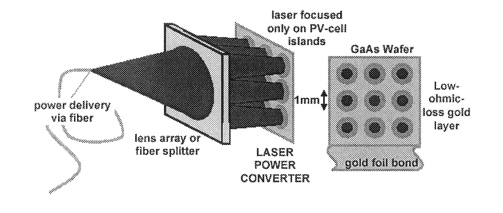
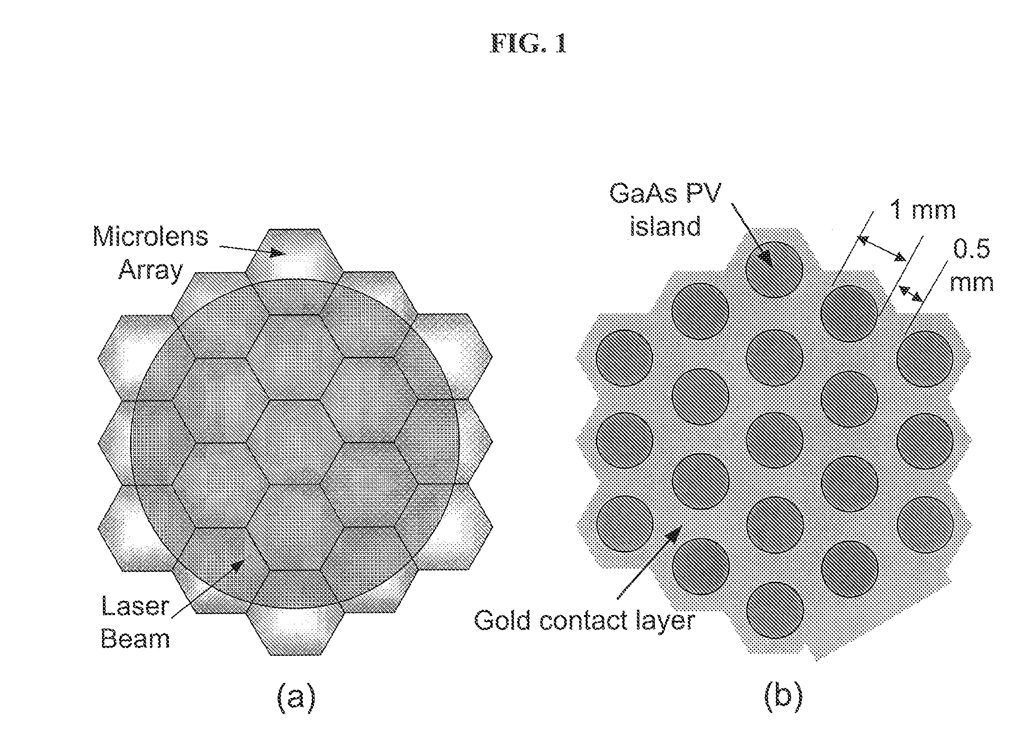
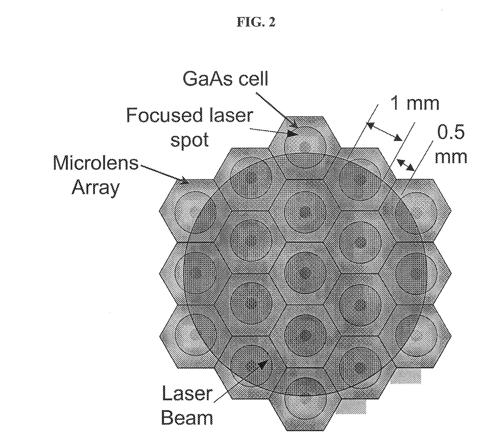
[0032]In one aspect of the present invention, a method and apparatus are provided to increase the efficiency of photovoltaic (PV) power conversion of lasers, delivered via optical fiber, into electrical power. A “laser” (from the acronym of Light Amplification by Stimulated Emission of Radiation) is an optical source that emits photons in a coherent beam. Throughout this...


PUM


Abstract

The present invention comprises a method and apparatus to increase the efficiency of photovoltaic conversion of light into electrical power and to achieve operation at higher optical power and therefore higher electrical power. Preferred embodiments increase the efficiency of photovoltaic power conversion of any source of a beam of photons by spatially dividing the beams into a plurality of individual beamlets, each beamlet focusing on an active photovoltaic region. The preferred architecture of the apparatus of the invention comprises spatially separated photovoltaic cells to substantially match the pattern of the spatially separated plurality of beamlets. Preferred embodiments result in a significant reduction in ohmic losses and current shunting, thereby increasing photovoltaic conversion efficiencies.

Description

FIELD OF THE INVENTION[0001]The present invention relates to conversion of photons, such as from a laser or light source, into electrical energy using photovoltaic cells. The present invention specifically relates to an apparatus and methods to increase the efficiency of energy conversion in photovoltaic devices, and further relates to operation at high optical power and the resulting electrical power in photovoltaic devices.BACKGROUND OF THE INVENTION[0002]Photovoltaic (PV) cells are semiconductor devices that convert photons of light (also known as photonic power, optical power, or light power) into electricity. The conversion utilizes the photovoltaic effect, which is generation of charge carriers (electrons and holes) in a light-absorbing material and separation of the charge carriers to conductive contacts that will transmit the electricity.[0003]Groups of PV cells can be configured into modules and arrays, which can be used to charge batteries, operate motors, and to power any...

Claims


Application Information

Patent Timeline
IPC IPC(8): H01L31/052
CPCY02E10/52H01L31/0543H01L31/0547
Inventor SUMIDA, DAVID S.JONES, DENNIS C.BRUESSELBACH, HANS W.NARAYANAN, AUTHI A.
Owner HRL LAB
Why Eureka
Try Eureka