Process for hot-forging synthetic ceramic

a synthetic ceramic and hot pressing technology, applied in the field of advanced ceramics, can solve the problems of high cost of specialized parts, high cost of hot pressing process, brittleness, etc., and achieve the effect of less porous and impermeable articles, zero open porosity

Active Publication Date: 2010-05-13
CERAMEXT LLC
View PDF18 Cites 2 Cited by
  • Summary
  • Abstract
  • Description
  • Claims
  • Application Information

AI Technical Summary

Benefits of technology

[0077]Another advantage of the present invention is that the solid compositions and corresponding articles of manufacture are impermeable without the need for glazing. The invention's impermeability is directly related to the fact that, unlike conventional synthetic rock materials, the composition and articles contain essentially zero open porosity, due to the continuous glass matrix structure surrounding crystallites distributed throughout therein. With the exception of certain rare vitreous expensive clay products, such as porcelain, conventional synthetic rock and ceramic products require glazing to achieve impermeability.
[0078]The synthetic ceramics of the embodiments of the invention contain substantially zero open porosity (less than 0.5% open porosity), which results in less porous and more impermeable articles as compared to conventional ceramic materials. Surprisingly, voids (closed pores) may be induced in applicant's invention to result in a lighter weight construction-type material, without compromising the invention's impermeable characteristics.
[0079]The feedstock materials used for the synthetic ceramics of the embodiments of the invention are typically waste materials or manufacturing byproducts that are particulate in their texture. Examples include fine particle residues from crushed rock quarries and fine grained fly-ash powder from coal burning power plants. Microscopic examination of these materials with the aid of a scanning electron microprobe instrument reveals very fine angular grains or clasts of various mineral components in the case of the pulverized quarry fines (FIG. 1) or spherical-shaped microscopic glass beads in the case of the fly-ash materials (FIG. 2). Incompletely melted remnants of these particulate or elastic sedimentary feedstock materials comprise the “aggregate” phase of the synthetic ceramics of the embodiments of the invention (FIGS. 3 and 4).
[0080]FIG. 1 shows a microscopic view of fine grained angular particles or clasts of a pulverized mineral and rock sediments found in crushed rock quarry fines and mine tailings. The particles seen here are composed of both single mineral grains and multi-mineral rock fragments. FIG. 2 shows a microscopic view of the fine grained fly-ash material largely composed of spherical-shaped glass beads with a smaller quantity of angular residual quartz. FIG. 3 shows a microscopic view of the incompletely melted remnants of the fine grained mineral and rock particles of the sedimentary feedstock materials that collectively comprise the “aggregate” phase of the hybrid rock material manufactured from mine tailings. The mineral grains are typically composed of more than one mineral type. In this example at least three mineral types are visible. FIG. 4 shows a microscopic view of the incompletely melted remnants of quartz and glass bead grains that collectively comprise the “aggregate” phase of the hybrid rock material manufactured from waste fly-ash material. The original spherical particle shape of the fly-ash and angular shape of quartz grains are recognizable.
[0081]Besides the incompletely melted remnants of the fine grained mineral and rock particles of sedimentary feedstock from mine tailings, the synthetic ceramic of the embodiments also could include a glass phase and a crystallite phase. The synthetic ceramics of the embodiments of the invention typically possess a “glass” phase and a “crystallite” phase similar to fine grained igneous rocks such as basalt. The glass phase is produced by the partial melting of minerals such as feldspar in the example of mine tailings waste or the melting of the glass beads that comprise the fly-ash waste feedstock materials. The crystallites (i.e., small mineral crystals that grow from the liquid “melt”) that occur in the hybrid rock material possess mineralogy similar to igneous rocks such as plagioclase feldspar and pyroxene also found in basalt; however, other crystallite mineralogy differ from those found in nature such as wollastonite and anhydrite. Collectively, this afore mentioned suite of crystallite mineralogies do not occur in any natural igneous rock as they do in the hybrid rock manufactured from the waste fly-ash materials (FIGS. 5 and 6). Typically, the glass phase is continuous or co-continuous while crystallite phase is continuous or discrete.
[0082]FIG. 5 shows a microscopic view of the microfabric of the hybrid rock material manufactured from waste fly-ash material. The remnant fly-ash and quartz clasts comprise the aggregate phase; the glass phase formed from the melting of the fly-ash forms the primary cement of the hybrid rock; and the crystallite phase is composed of small crystals of plagioclase, wollastonite, pyroxene, and anhydrite (shown in FIG. 6). FIG. 6 shows as microscopic view of larger crystallites of newly formed anhydrite in the fly-ash hybrid rock. The anhydrite crystallites often arrange in linear fashion to form pseudo- or faux-marbling textures on the surface of the ceramic tile.

Problems solved by technology

Graphite parts oxidize over time and are highly susceptible to wear, which makes the hot pressing process expensive and only in use for manufacture of high-cost specialized parts.
The conventional ceramic tiles are rigid, brittle and cured to a permanently set (thermosetting) composition.
Thus, the conventional ceramic tiles cannot be recycled by and reformed by heating and melting the ceramic tile like a thermoplastic polymer can be recycled and reformed.
McGee's method requires a complicated and expensive apparatus to remove the sides of the mold and avoid friction.
The higher processing temperature is more expensive to operate, and tends to liquefy a greater portion of the starting material, resulting in a weaker final product.

Method used


Image

  • Process for hot-forging synthetic ceramic
  • Process for hot-forging synthetic ceramic
  • Process for hot-forging synthetic ceramic

Examples


example 1

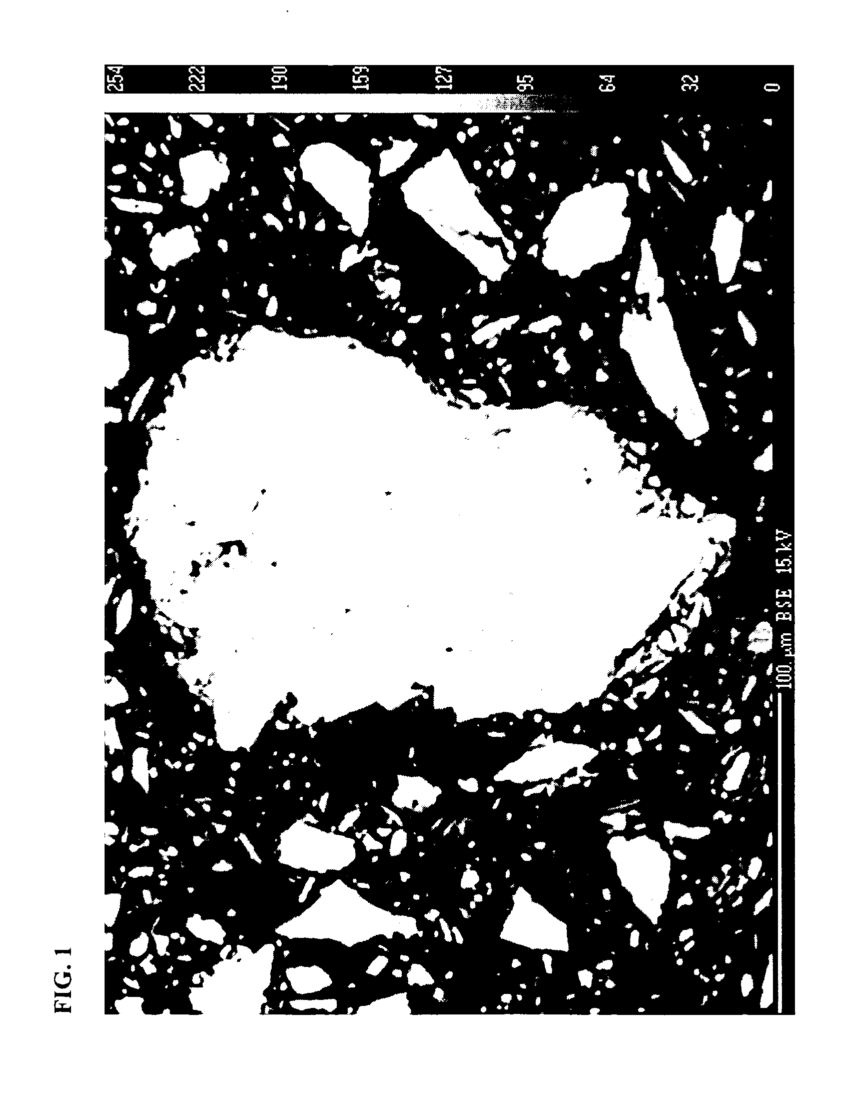
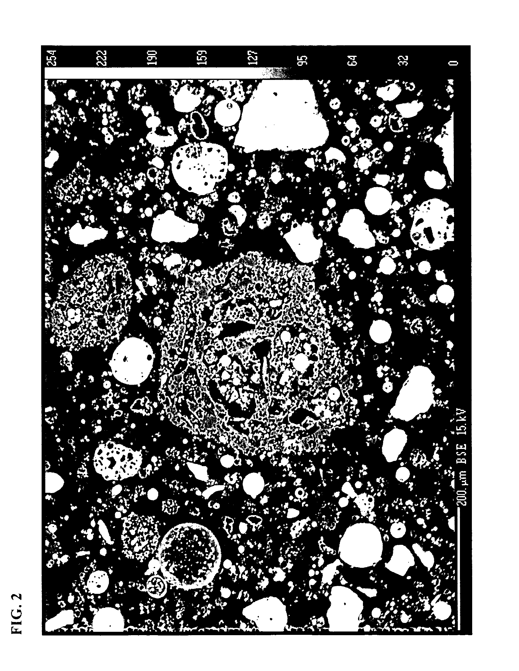
[0099]Quarry Fines A were dried, screened through a 200-micron screen, mixed with 6% water, pressed into a green tile blank at 25° C. and 19 MPa (2,800 psi), which was then dried to make a green tile blank before subsequent work. The cold, dry, green tile blank with a square shape and an edge dimension of about 32.4 cm (12.75 in.) was placed in a hot furnace at about 1185° C. on a platform of mullite tubes. The tile blank rapidly came up to the furnace temperature, and it was held there for 10 to 15 minutes. Using a long steel fork, the tile blank was then transferred in less than about 10 seconds to a press, where it was placed entirely within the cavity of a lower die of a 33.6-cm (13.25-inch) square tile mold. The upper die was lowered and approximately 11 MPa (1600 psi) was applied to the tile for about 1 second. The forged tile was then removed and transferred in less than 10 seconds to a cooling furnace at 800° C. FIG. 10 shows a SEM of a hot-forged tile made by the process of...

example 2

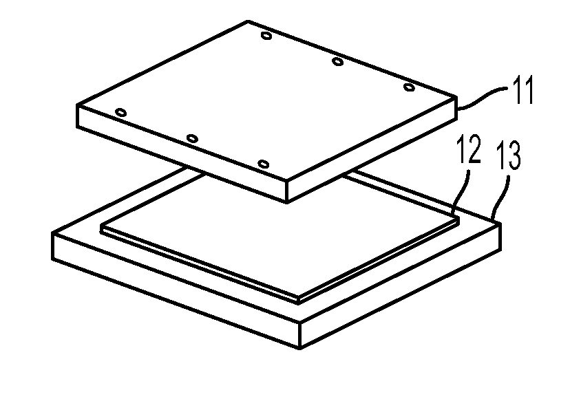
[0101]Quarry Fines A were dried, screened through a 200-micron screen, mixed with 6% water, pressed into a green tile blank at 25° C. and 19 MPa (2,800 psi), which was then dried to make a green tile blank before subsequent work. The cold, dry, green tile blank with a square shape and an edge dimension of about 32.4 cm (12.75 in.) was placed in a hot furnace at 1185° C. on a pre-heated flat plate of nitrided silicon carbide (Advancer® SiC) The tile blank rapidly came up to the furnace temperature, and it was held there for 10 to 15 minutes. Using a long steel fork, the tile blank was then transferred in about 7 seconds to a press. Referring now to FIG. 13 and its subfigures, the preheated tile blank 22 was placed in a press over a set of four square cavities 25, each about 10.8-cm (4.25-inch) square. As shown in FIGS. 13A and 13B, an upper set of dies 21, affixed to a die platen 24, was lowered and punched through the hot tile blank, leaving an unpressed “picture frame” of scrap 26 ...

example 3

[0104]Quarry Fines A were dried, screened through a 200-micron screen, mixed with 6% water, pressed into a green tile blank at 25° C. and 19 MPa (2,800 psi), which was then dried to make a green tile blank before subsequent work. The cold, dry, green tile blank with a square shape and an edge dimension of about 32.4 cm (12.75 in.) was placed in a hot furnace at 1185° C. on a flat plate of nitrided silicon carbide (SiC) The tile blank rapidly came up to the furnace temperature, and it was held there for 10 to 15 minutes. Using a long steel fork, the tile blank was then transferred in about 4 seconds to a press. Referring now to FIG. 14 and its subfigures, the preheated tile blank 32 was placed in a press over a cavity 35 of a lower die 33 of a 33.6-cm (13.25-inch) square tile mold. Because the tile blank was wider than the lower die cavity 35, it did not sit inside the cavity, but rather was supported over it, approximately centered. As shown in FIG. 14A, which shows the bottom face ...


PUM

PropertyMeasurementUnit
temperatureaaaaaaaaaa
pressureaaaaaaaaaa
pressureaaaaaaaaaa

Abstract

The embodiments of the invention are directed to a synthetic ceramic comprising pyroxene-containing crystalline phase, a clast, and a glass phase, wherein at least a portion of the synthetic ceramic is plastically deformable in a certain temperature range. Other embodiments of the invention relate to a method of making a synthetic ceramic, comprising heating a green ceramic material to 900-1400° C., to a temperature sufficient to initiate partial melting of at least a portion of the green ceramic material, transferring the heated green ceramic material to a press, pressing the heated green ceramic material in a die at 1,000 to 10,000 psi, and transferring the heated, pressed green ceramic material to a furnace for cooling to form the synthetic ceramic.

Description

RELATED APPLICATIONS [0001]This application is related to U.S. Ser. No. 11 / 213,218, filed Aug. 25, 2005, entitled “Synthesized Hybrid Rock Composition, Method, and Article Formed by the Method,” which is incorporated herein by reference. This application is also related to U.S. Ser. No. 09 / 596,271, now U.S. Pat. No. 6,547,550, issued on Apr. 15, 2003, entitled “Apparatus for hot vacuum extrusion of ceramics,” U.S. Ser. No. 10 / 382,765, filed Mar. 5, 2003, entitled “Method and apparatus for hot vacuum extrusion of ceramics,” all of which are incorporated herein by reference.FIELD OF INVENTION [0002]Embodiments of the invention relate to the field of advanced ceramics, particularly to the composition and manufacture of synthetic ceramic (also referred herein as a “hybrid rock material” or as “manufactured stone”) such as ceramic tile of a ceramic composite that is plastically deformable at high temperature, and otherwise strong, with low porosity.BACKGROUND [0003]“Uniaxial hot pressing...

Claims


Application Information

Patent Timeline
Patent Type & Authority Applications(United States)
IPC IPC(8): B28B3/20C04B33/32
CPCC04B33/13C04B33/323C04B33/1355C04B33/20C04B33/326C04B35/18C04B35/20C04B35/6263C04B2235/3201C04B2235/3206C04B2235/3208C04B2235/3232C04B2235/3262C04B2235/3272C04B2235/3427C04B2235/3436C04B2235/3445C04B2235/3454C04B2235/3463C04B2235/3472C04B2235/3481C04B2235/6021C04B2235/6565C04B2235/72C04B2235/726C04B2235/727C04B2235/77C04B2235/80C04B2235/96C04B2235/9623C04B2235/9638C04B33/1324Y02P40/60
Inventor WARMERDAM, JERRYCOCHRAN, JOSEPH R.GUENTHER, ROSSWOOD, JAMES L.VILLWOCK, ROBERT D.
Owner CERAMEXT LLC
Why Eureka
Try Eureka