Thermoplastic coating for composite structures

a composite structure and thermoplastic coating technology, applied in coatings, layered products, chemical instruments and processes, etc., can solve the problems of significant degradation and damage of composite structures applied to the exterior of ships and aircraft, the possibility of permanent damage of a given vessel or aircraft, and the possibility of significant degradation and damage of structures, etc., to achieve uniform thickness and morphology, reduce the occurrence of partially unmelted or heat-damaged thermoplastics, and reduce the effect of porous and/or permeability

Active Publication Date: 2005-01-27
NORTHROP GRUMMAN SYST CORP
View PDF23 Cites 3 Cited by
  • Summary
  • Abstract
  • Description
  • Claims
  • Application Information

AI Technical Summary

Benefits of technology

[0007] A technical advantage of certain embodiments of the present invention is that the heating of the tool may more fully melt and fuse together the thermoplastic particles during deposition, resulting in a coating that may be of a more uniform thickness and morphology and be less porous and / or permeable. In particular embodiments, the occurrence of partially un-melted or heat-damaged thermoplastic may be reduced.
[0008] Another technical advantage certain embodiments of the present invention is a reduction in local overheating of the tool caused by the thermal spray gun. This reduction may result in the avoidance of damage or deformation of the tool during thermoplastic deposition. Such reduction may preserve the integrity of any release coating applied to the tool, increasing the ease with which the thermoplastic-coated composite is removed from the tool after the curing step.

Problems solved by technology

Composite structures applied to the exterior of ships and aircraft can experience significant degradation and damage due to their exposure to erosion and environmental attack.
In this regard, such structures are constantly subjected to oxidation, moisture, fouling, salt-spray, UV radiation, chemicals, and high and low temperatures, among other things, that can cause such structures to experience significant degradation and damage over time.
As a consequence, such structural components are often constantly repaired or replaced to prevent the possibility that a given vessel or aircraft will be damaged permanently, if not destroyed.
However, when a high melt temperature, high performance thermoplastic such as liquid crystal polymer (LCP) is thermally sprayed on a composite with moderate temperature resistance, out-gassing of moisture and volatiles from the composite substrate can occur which can degrade the structural morphology of the coating.

Method used


Image

  • Thermoplastic coating for composite structures
  • Thermoplastic coating for composite structures
  • Thermoplastic coating for composite structures

Examples


Embodiment Construction

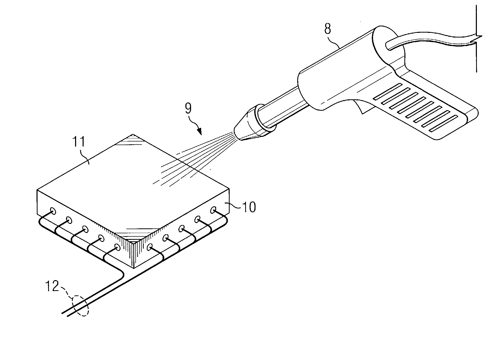
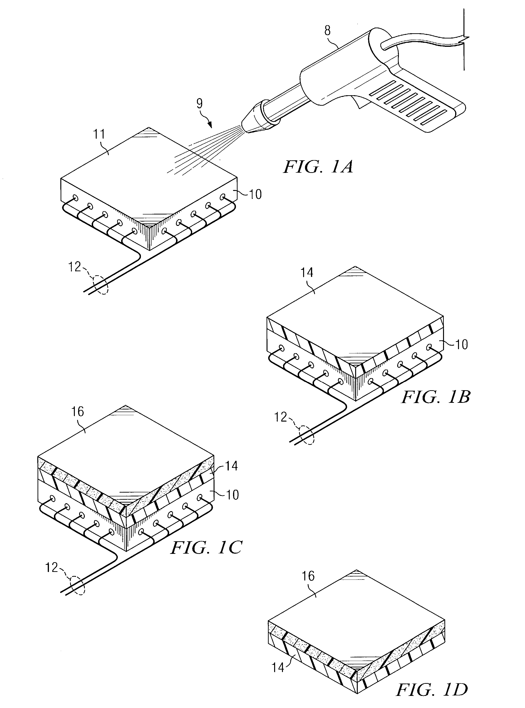
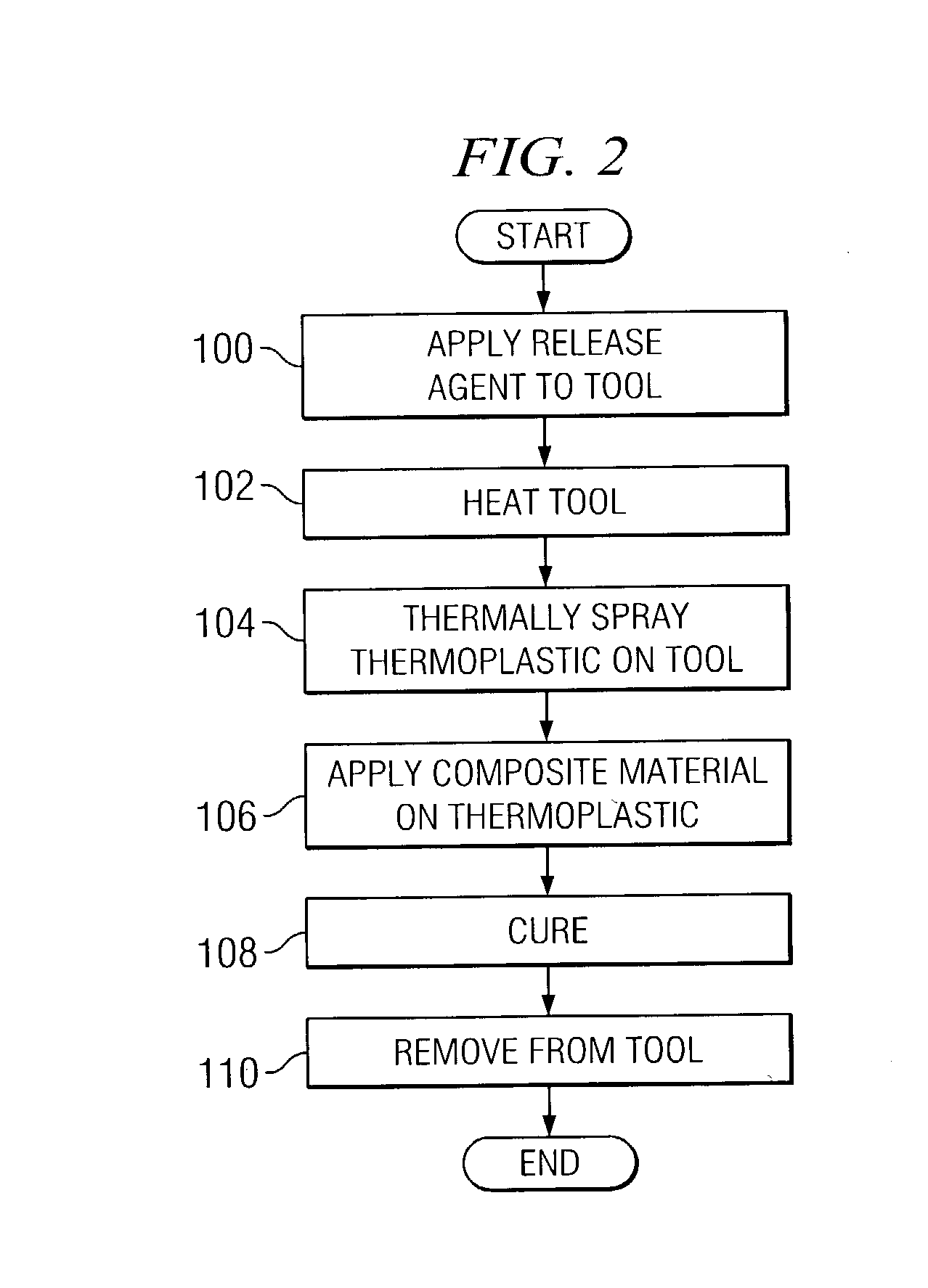
[0013]FIGS. 1A-1D are block diagrams illustrating a method for thermoplastic coating of a composite structure in accordance with one embodiment of the present invention. FIG. 1A illustrates deposition of a thermoplastic 9 on a working surface 11 of a tool 10 in accordance with one embodiment of the present invention.

[0014] Tool 10 reflects the desired shape of the outer surface of the final composite structure and may be formed from a metal material such as aluminum or steel. In a particular embodiment, the tool 10 is coated with Frekote™, Teflon™, or another suitable release coating before deposition of the thermoplastic 9. It will be understood that tool 10 may be formed from other suitable materials, such as ceramic. In the illustrated embodiment, tool 10 is heated before thermoplastic deposition by internal heaters built into the tool 10 powered by electrical or other suitable methods 12 to bring the tool 10 to a temperature sufficient to help in the thermoplastic melt and coat...


PUM

PropertyMeasurementUnit
temperatureaaaaaaaaaa
melting temperatureaaaaaaaaaa
temperatureaaaaaaaaaa

Abstract

A method of thermoplastic coating composite structures includes heating a tool. A thermoplastic layer is deposited onto the heated tool by thermal spraying a thermoplastic on the heated tool. Composite material is applied onto the thermoplastic layer. The thermoplastic layer and the composite material are then cured.

Description

TECHNICAL FIELD OF THE INVENTION [0001] This invention relates generally to the field of materials construction and, more specifically, to a method of thermoplastic coating composite structures. BACKGROUND OF THE INVENTION [0002] Composite structures are desirable in many industries for many applications. The aerospace industry, for example, uses composite structures extensively because, among other desirable attributes, composites have high strength-to-weight ratios. Because of the ever increasing use of composite structures throughout industry, manufacturers are continually searching for better and more economical ways of fabricating composite structures. [0003] Composite structures applied to the exterior of ships and aircraft can experience significant degradation and damage due to their exposure to erosion and environmental attack. In this regard, such structures are constantly subjected to oxidation, moisture, fouling, salt-spray, UV radiation, chemicals, and high and low temp...

Claims


Application Information

Patent Timeline
Patent Type & Authority Applications(United States)
IPC IPC(8): B05D1/10B05D1/28B29C37/00B29C41/20
CPCB05D1/10B05D1/286B29C37/0032B32B2037/243B29C41/20B32B37/04B29C37/0067
Inventor DIMARZIO, DONWEIZENECKER, CHARLESCHU, STEVEANTON, DOM
Owner NORTHROP GRUMMAN SYST CORP
Why Eureka
Try Eureka