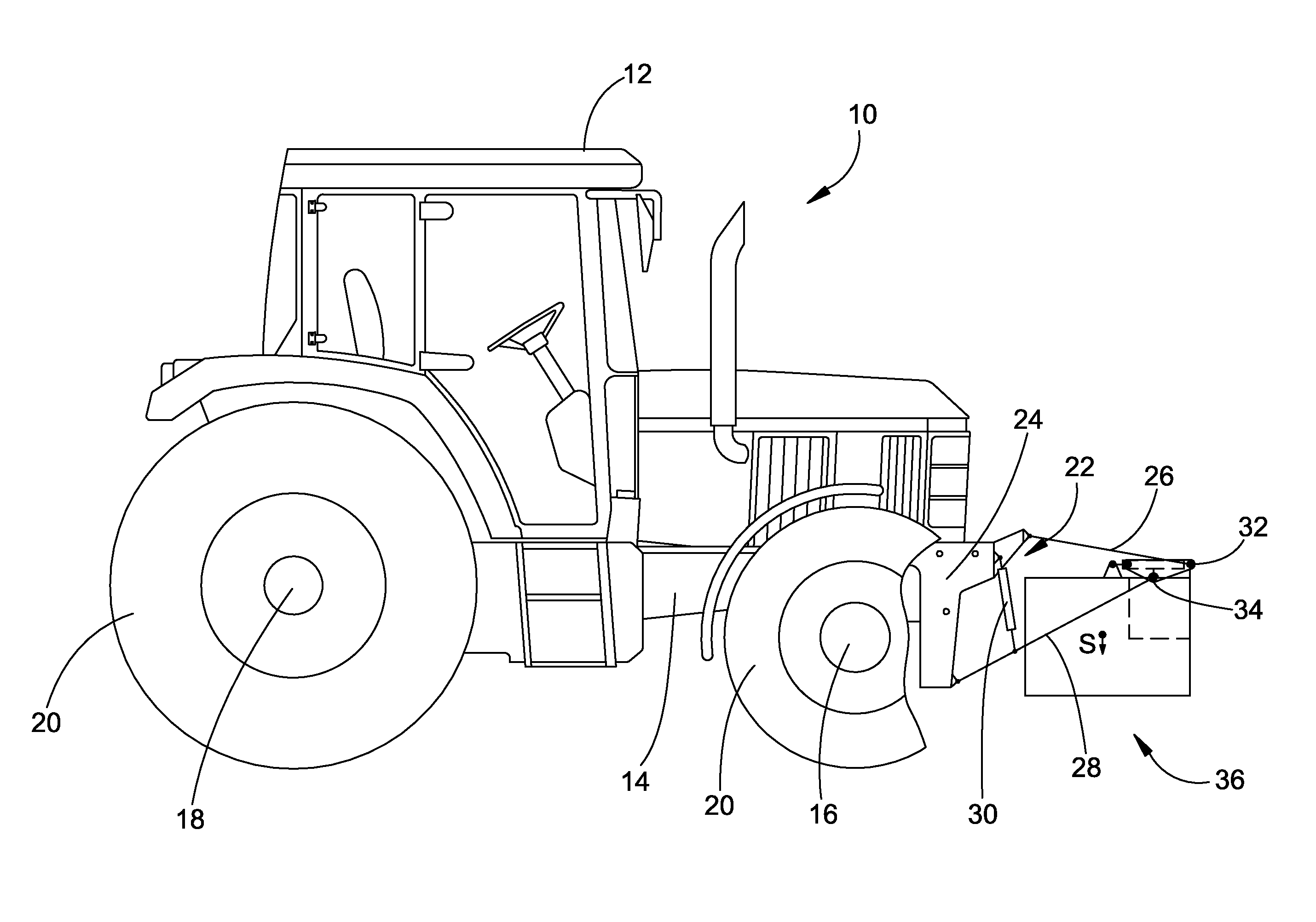
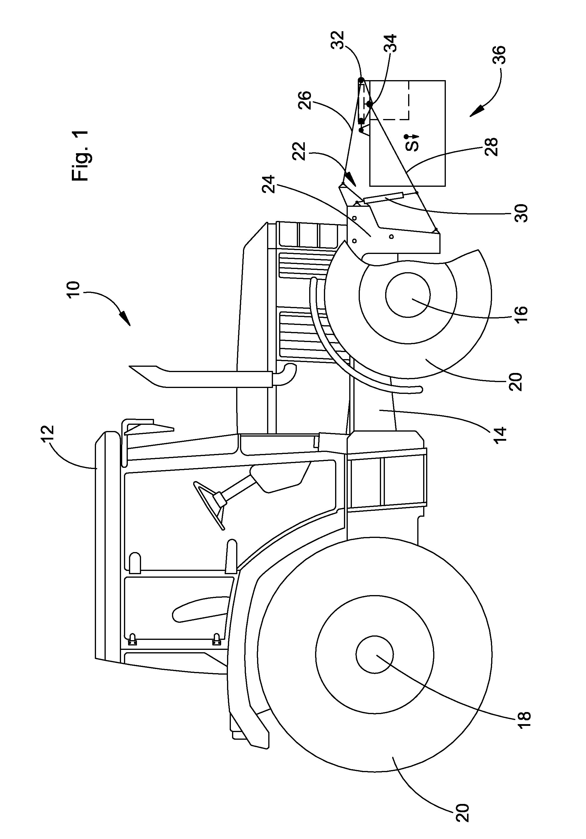
[0009]These objects are achieved by the present invention, wherein a balancing system is configured in so that the center of gravity of the balance weight is below the pivot axis in the position close to the vehicle and pivoting devices are provided by means of which the balance weight can be pivoted about the pivot axis in such a way that it can be moved from the position close to the vehicle to a position distant from the vehicle, where the balance weight is located in the position close to the vehicle at a lower location of its center of gravity than in the position more distant from the vehicle. A balancing system, according to the invention, makes it possible to adjust the supplementary weight applied to the front wheels of the vehicle by moving it in the longitudinal direction and to adjust it optimally to the existing operating conditions. In that way an altogether lower balancing
mass can be applied for the balancing. Since the balance weight can be moved it can be brought into an intermediate position very simply. This simplifies the removal or disassembly of the balance weight as well as the application or the mounting of the balance weight. Preferably the balancing system can be coupled to a three point implement hitch of an
agricultural tractor. This permits a simple handling of the balance weight where the balancing system can be engaged by the mounting pins provided on the balance weight and engaged by the lower steering arms of the three point implement hitch. The position of the center of gravity of the balance weight is arranged below the pivot axis defined by attachment pins of the balance weight; this makes it possible by pivoting the balance weight forward about the pivot axis to shift the weight from a lower position close to the vehicle to a higher position more distant from the vehicle. Thereby higher loads are possible for example for operation on public roads without any greater additional cost and lower overall fuel consumption is attained. In addition due to the lower position of the center of gravity of the balance weight in the position close to the vehicle the protection of passengers and the vehicle is increased since obstacles during collisions, for example, during an accident with a passenger vehicle are collided with in a lower position of the center of gravity so that a roll-over can also be avoided. The position of the balance weight close to the vehicle provides a maximum mobility of the vehicle since the balance weight does not extend as far in the forward direction. In the position of the balance weight close to the vehicle with lower center of gravity of the balance weight, the safety of operating the vehicle is also increased in the case of operating around a curve or along a side slope.
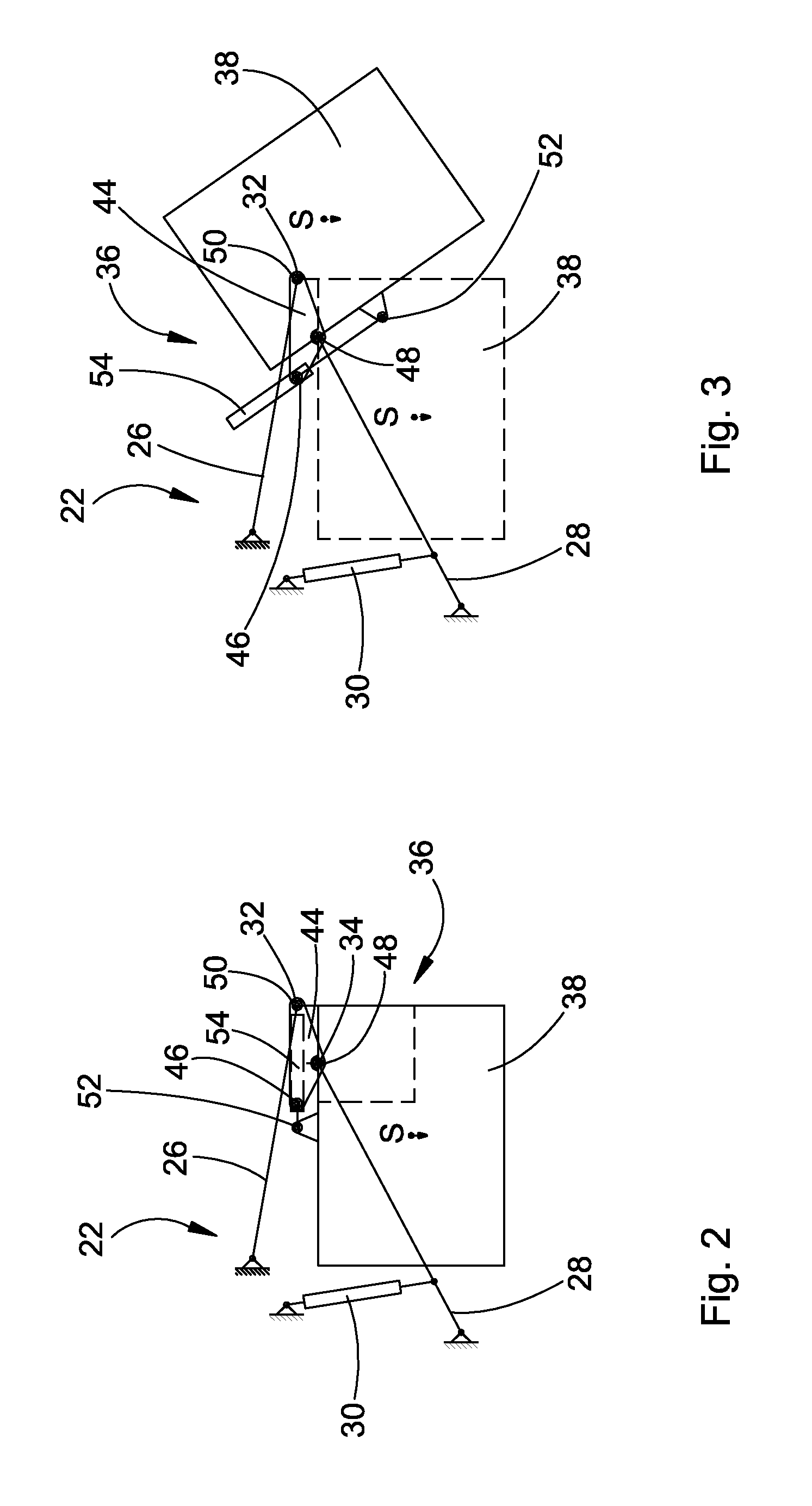
[0012]In a further preferred embodiment the pivoting devices are provided with at least one sheet
metal steering device with at least three connecting points and a steering arm, adjustable in length in addition to the take-up bearing at the balance weight, where the sheet
metal steering device is connected at a (first) connection point by means of the steering arm that is adjustable in length and is connected so as to rotate with the take-up bearing and to a (second) further connecting point coaxially to the axis of rotation and free to rotate with the balance weight, in such a way that a pivoting of the balance weight relative to the sheet
metal steering device can be attained by a change in the length of the steering arm that is adjustable in length, where the sheet metal steering device can be coupled to a further (third) connecting point to the steering arm of a three point implement hitch, preferably the upper steering arm. Since the second connection point of the sheet metal steering device is arranged coaxially to the pivot axis or to the take-up pin, during the
coupling of the balance arrangement of a three point implement hitch the position of the second connecting point is established or provided as input to the take up pin of the balancing system. As long as these (are adjustable in height or in length) are configured as adjustable, by readjusting the lower steering arms of the pivot axis of the balancing system and with it the position of the second connecting point can be varied, or readjusted, or shifted. Moreover, in the case of
coupling of the balancing system to a three point implement hitch the position of the third connecting point of the sheet metal steering device is also established by the steering arm of the three point implement hitch (in particular, the upper steering arm), where the position of the third connecting point can be varied or repositioned or adjusted by readjusting the lower steering arms. Thereby the positions of the second and third connecting points (and thereby also the position of the first connecting point) can be defined, varied or adjusted or shifted when the balancing system is coupled by adjusting the lower steering arm relative to a
vehicle frame equipped with a three point implement hitch. Moreover, it is also possible to configure the steering arm connected to the third connecting point as variable in length, in order to create additional possibilities for the positions of the connecting points of the sheet metal steering device.
[0013]Preferably, the steering arm(s) that can be adjusted in length is (or are) configured as an
actuator, particularly as a
hydraulic cylinder. However, it is also conceivable to select another method of actuation, for example, an electric, mechanical or pneumatic method of actuation of a cylinder. In that way, the
actuator can be configured as an
electric motor, for example, a spindle motor. A corresponding arrangement with a
rope pull is also conceivable in order to configure the
actuator purely mechanically. Preferably the actuator is connected in such a way that by actuating the actuator in interplay of the balancing system with the steering arms of the three point implement hitch a guided movement of the balance weight can be performed. Thereby an assurance is provided for an operator to attain a variation, or shifting or readjustment of the balance weight by
remote control as well as during changing operating conditions and can react rapidly so as to optimize the balancing system.
[0014]In a preferred embodiment of the invention the pivoting devices extend at least partially through a recess provided on the balance weight, where the recess is preferably configured as central to a central longitudinal axis of the vehicle or the
vehicle frame. Depending on the configuration the pivoting devices can also extend at least partially through a recess that is arranged on the vehicle body and / or on a
vehicle frame and / or a take up arrangement arranged on the vehicle body or vehicle frame, where this is also configured correspondingly centrally. The recess or recesses permit a most compact configuration of the pivoting devices, particularly the sheet metal steering device in interaction with the steering arm(s) that are adjustable in length, since the pivoting devices perform their pivoting motion generally within the recess. The central arrangement of the recess provides for a most possibly symmetrical distribution of the balance weight or the entire balancing system.
[0017]Moreover, the balance weight may be configured in such a way that it is arranged at least partially underneath the vehicle body in its position close to the vehicle. Thereby, for example, a further center of gravity
relocation downward can be attained and, on the other hand, the projection of the balance weight ahead of the vehicle body can be reduced, whereby the aforementioned advantages relative to a lower center of gravity and for a maximum mobility can be expressed even more strongly.
[0019]In a preferred embodiment of the invention the steering arms of the balancing system or of the three point implement hitch can be immobilized by means of an immobilizing arrangement in the adjustable positions. This provides the assurance that the balance weight is retained safely and preferably without any play in a position close to the vehicle as well as a position distant from the vehicle. Here it is also possible to provide positions between the position close to the vehicle and the position distant from the vehicle so that they can be immobilized also, so that a balancing with a fine calibration can be performed. Preferably the immobilizing arrangement includes the steering arm or arms of the pivoting arrangement or of the three point implement hitch that can be immobilized in a certain position hydraulically or pneumatically, or mechanically, or electrically, that is they can be retained or blocked, so that the adjustable steering arms remain in a retained or a blocked position. Such an immobilizing arrangement or blocking arrangement can be applied to a steering arm that is adjustable in its length that includes a hydraulic actuator, and performed for example, hydraulically. An electrically operated spindle motor or
stepper motor operating as an actuator can, for example, remain in its position and block the steering arm arrangement by corresponding electronic control signals.


