Electrochemical Device Comprising One or More Fuel Cells

Inactive Publication Date: 2010-05-13
SHANGHAI HORIZON FUEL CELL TECH
View PDF10 Cites 0 Cited by
  • Summary
  • Abstract
  • Description
  • Claims
  • Application Information

AI Technical Summary

Benefits of technology

[0017]The area of the said separation sheet which is in contact with main surface is, preferably, 25%-75% of the area of the main surface. The contact area can only discharge moisture through diffusion in a properly oriented gas diffusion layer. So the bigger the contacting area is, the better the humidifying effect will be.
[0019]Such a change could influence the performance of the device and make its design more complicated.
[0022]Compared with the prior art, the present invention has advantages of both an open cathode structure and a closed cathode structure, and produces better self-moisturizing effects at lower cost with reduced volume and weight.

Problems solved by technology

Due to the migration of the electroosmosis, the hydrogen electrode is short of water, which could cause the fuel cell to work improperly.
In order to obtain humidification, which is an effective way to maintain the water in balance, currently people use a humidifying system, but this system can make the fuel cell system complicated and the cost high.
The first one is to make water in the proton exchange membrane through a catalyzing reaction, but this process has the disadvantages of having large internal resistance and the possibility that a water shortage develops due to the absence of a matching water supply.
Although this goal can be realized commercially, it will complicate the fuel cell structure and is not convenient in mass production.
Some disadvantages are that the air flow with a large stoich takes away too much water while eliminating heat.
Although these disadvantages can be overcome to some extent by increasing the cathode diffusion layer density and hydrophilicity, the results are not good with the side effect of sacrificing the output current density.
Some disadvantages are that the fuel cell stack structure becomes complicated as does the periphery, control system and that it is accompanied by high cost, big size and heavy weight.
This water will be discharged in the way of gas or liquid through the cathode, which will cause the device to consume more water.
So both the cathode open style structure and the cathode close style structure have the same problems as the fuel cell mentioned above.

Method used


Image

  • Electrochemical Device Comprising One or More Fuel Cells
  • Electrochemical Device Comprising One or More Fuel Cells
  • Electrochemical Device Comprising One or More Fuel Cells

Examples


Embodiment Construction

[0026]For purposes of this disclosure, the following definitions apply:

[0027]Mass transfer contact refers to contact between surfaces that can have matter and mass exchange which differs from contact between surfaces which transfer heat, vibration, current, etc.

[0028]The device described includes all the parts, accessories except the air source that generate air flows.

[0029]The stack is a generalized stack and may include only one electrochemistry cell comprising piled structure with end plates at both sides.

[0030]The electrochemical reaction main surface is wider than that of the electrode surface commonly referred to in the art. It may include the gas diffusion layer connected to the electrode.

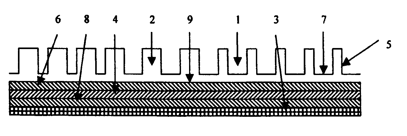
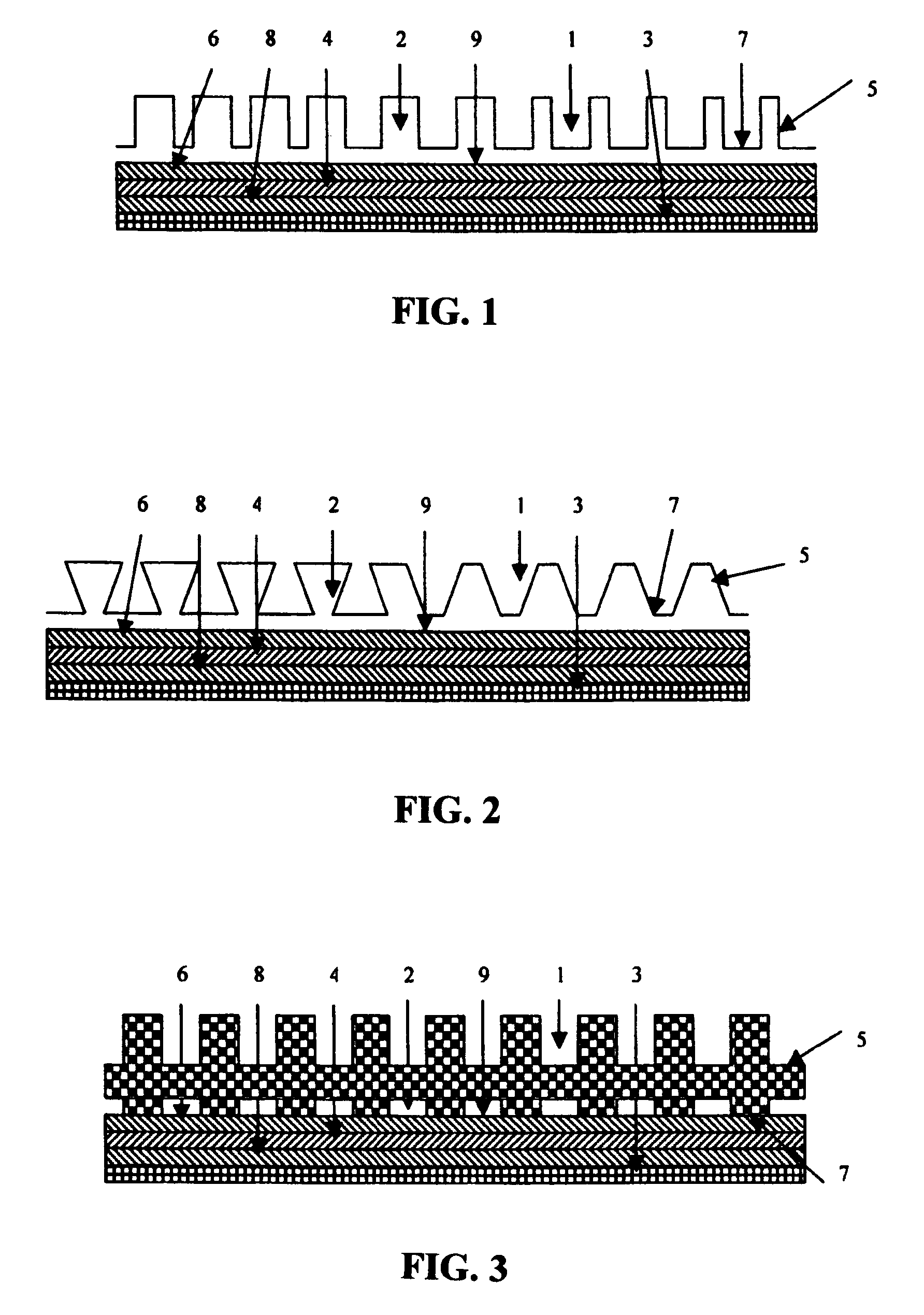
[0031]The elements numbered in the drawings correspond to the following descriptions:[0032]10. Groove area of all the air flow(s) that is / are not in mass transfer contact with the main surface[0033]11. Groove area of all the air flow(s) that is / are in mass transfer contact with the main surf...


PUM


Abstract

An electrochemical device comprising one or multiple self-humidifying electrochemical fuel cells, wherein each electrochemical fuel cell comprises a main surface (9) which can be used for an electrochemical reaction and can consume the oxygen contained in the air. A single air flow enters into the fuel cell and is divided into at least two parts of air flow inside the fuel cell. At least one of these parts of air flow has mass transfer contact with the main surface (9). Otherwise, at least another part of air flow has no mass transfer contact with the main surface (9). The air flow is divided by a separation sheet (5).

Description

TECHNICAL FIELD[0001]The present invention relates to the electrochemical and chemical fields, and more particularly to an electrochemical device comprising one or multiple fuel cells.BACKGROUND OF THE INVENTION[0002]The fuel cell uses hydrogen as its fuel and oxygen as oxide. The hydrogen and oxygen react with each other to generate electricity and water without combustion. They are environmentally friendly, have high energy density, and are an efficient, reliable electricity generator for various applications in submarine, vehicle, laptop and mobile phone applications especially as a result of improving fuel cell technologies.[0003]When the fuel cell is working, the oxygen electrode will generate water. Due to the migration of the electroosmosis, the hydrogen electrode is short of water, which could cause the fuel cell to work improperly. So, in order to maintain the fuel cell working in a stable and proper way, it is necessary to keep the water in the fuel cell in balance. In ord...

Claims


Application Information

Patent Timeline
IPC IPC(8): H01M2/00
CPCH01M8/0247Y02E60/50H01M8/24H01M8/04126H01M8/026Y02P70/50
Inventor KOSCHANY, ARTHUR
Owner SHANGHAI HORIZON FUEL CELL TECH
Why Eureka
Try Eureka