USB-Attached-SCSI Flash-Memory System with Additional Command, Status, and Control Pipes to a Smart-Storage Switch

a flash memory system and smart storage switch technology, applied in the direction of memory adressing/allocation/relocation, digital storage, instruments, etc., can solve the problems of limited performance, cost and size sensitive small devices, and limitations on writing, etc., to achieve the effect of fast performan

Inactive Publication Date: 2010-05-13
SUPER TALENT TECH CORP
View PDF2 Cites 74 Cited by
  • Summary
  • Abstract
  • Description
  • Claims
  • Application Information

AI Technical Summary

Benefits of technology

[0044]Because data storing and reading in a flash memory device is necessary for access and verification purpose, speed is also a major concern of the device performance. According to additional aspects of the present embodiment set forth below, a method of dual-channel parallel and interleave access flash is implemented in an electronic data flash card for faster performance than is possible using conventional methods.

Problems solved by technology

These small devices are often cost and size sensitive.
Pages in the same block may have to be erased together, and limitations on writing may exist, such as only being allowed to write each page once between erases.
The USB 3.0 bus standard uses two pairs of differential lines that are time-duplexed, or used for transmission in both directions, but at different times. This may limit performance when data needs to be sent in both directions at the same time.
Legacy host systems are not equipped for the newer bus protocols since these legacy systems are older and were designed before the new bus protocols were available.
Bridges are often slow since all protocol layers may be present and are traversed.
When multiple bus standards are present on a host system, several bridges may be used in series, causing increased delays for multiple successive format conversions by multiple bridge devices.

Method used


Image

  • USB-Attached-SCSI Flash-Memory System with Additional Command, Status, and Control Pipes to a Smart-Storage Switch
  • USB-Attached-SCSI Flash-Memory System with Additional Command, Status, and Control Pipes to a Smart-Storage Switch
  • USB-Attached-SCSI Flash-Memory System with Additional Command, Status, and Control Pipes to a Smart-Storage Switch

Examples


Embodiment Construction

[0077]The present invention relates to an improvement in solid-state-drive (SSD) flash architectures. The following description is presented to enable one of ordinary skill in the art to make and use the invention as provided in the context of a particular application and its requirements. Various modifications to the preferred embodiment will be apparent to those with skill in the art, and the general principles defined herein may be applied to other embodiments. Therefore, the present invention is not intended to be limited to the particular embodiments shown and described, but is to be accorded the widest scope consistent with the principles and novel features herein disclosed.

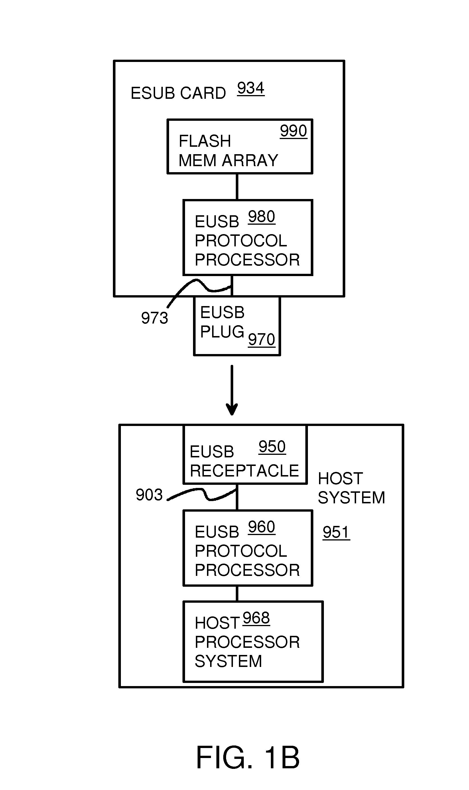
[0078]FIG. 2 shows an extended USB device connected to a EUSB host. Application program 32 on a host needs to read data that is stored in flash memory 30 on EUSB device 20. Application program 32 sends a data-read request to a device driver for the flash in device modules 34, which activate EUSB Bulk-Only-T...


PUM


Abstract

An electronic flash-memory card has additional pipes for commands and status messages so that data pipes are not clogged with commands and status messages, allowing for a higher data throughput. The command and status pipes are activated when a UAS/BOT detector detects that a host is using a USB-Attached-SCSI (UAS) mode rather than a Bulk-Only-Transfer (BOT) mode. The host can send additional commands and data without waiting for completion of a prior command when operating in UAS mode but not while operating in BOT mode. A command queue (CQ) in the device re-orders commands for accessing flash memory and merges data in a RAM buffer. Smaller 1 KB USB packets in the data pipes are merged into larger 8 KB payloads in the RAM buffer, allowing for more efficient flash access.

Description

RELATED APPLICATION[0001]This application is a continuation-in-part (CIP) of “PCI EXPRESS-COMPATIBLE CONTROLLER AND INTERFACE FOR FLASH MEMORY”, U.S. Ser. No. 12 / 254,428, filed on Oct. 20, 2008; which is a Division of “PCI EXPRESS-COMPATIBLE CONTROLLER AND INTERFACE FOR FLASH MEMORY”, U.S. application Ser. No. 10 / 803,597, filed on Mar. 17, 2004, now U.S. Pat. No. 7,457,897.[0002]This application is also a CIP of co-pending U.S. patent application for “SYSTEM AND METHOD FOR PROVIDING SECURITY TO A PORTABLE STORAGE DEVICE”, U.S. application Ser. No. 11 / 377,235, filed on Mar. 15, 2006.[0003]This application is also a CIP of “FLASH MEMORY CONTROLLER FOR ELECTRONIC DATA FLASH CARD”, U.S. application Ser. No. 11 / 466,759, filed on Aug. 23, 2006.[0004]This application is a continuation-in-part (CIP) of co-pending U.S. patent application for “HIGH-LEVEL BRIDGE FROM PCIE TO EXTENDED USB” Ser. No. 11 / 926,636, filed on Oct. 29, 2007.[0005]This application is also a CIP of co-pending U.S. patent...

Claims


Application Information

Patent Timeline
Patent Type & Authority Applications(United States)
IPC IPC(8): G06F12/00G06F12/02G06F13/00
CPCG06F3/0613G06F3/0661G06F3/0688G11C2216/30G11C13/0004G11C16/102G11C11/5678
Inventor LEE, CHARLES C.YU, FRANKMA, ABRAHAM C.
Owner SUPER TALENT TECH CORP
Why Eureka
Try Eureka