Hybrid hydraulic drive system for all terrestrial vehicles, with the hydraulic accumulator as the vehicle chassis
What is AI technical title?
AI technical title is built by Patsnap AI team. It summarizes the technical point description of the patent document.
a hybrid hydraulic and vehicle chassis technology, applied in the direction of fluid couplings, couplings, transportation and packaging, etc., can solve the problems of not solving the full energy consumption of those vehicles, the series hybrid hydraulic system goes beyond the parallel system, and lacks a good and precise flow control-speed, etc., to achieve safer operation, improve efficiency, and simplify control
Inactive Publication Date: 2010-05-20
ROSMAN ALLAN
View PDF60 Cites 16 Cited by
Summary
Abstract
Description
Claims
Application Information
AI Technical Summary
This helps you quickly interpret patents by identifying the three key elements:
Problems solved by technology
Method used
Benefits of technology
Benefits of technology
[0015]The use of the accumulator of a hydraulic system as the main chassis of the vehicle overcomes one of the major issues for the implementation of hydraulics, the large weight per unit of stored energy. At the same time this development allows for much larger accumulators, as the accumulator weight is no longer an issue. This new available dimension allows for periods of operation without the prime mover running, saving a large portion of fuel and emissions, as engines and electric motors consume unloaded about 40% of the maximum consumption or current in the case of the electric motors.
[0018]The coordination of the operation of the system is done with computer and copyrighted software. One version of the controls allows for the use of one pedal or joystick to control speed, direction, acceleration and braking and with a joystick one can add steering, for a vehicle much simpler to control and much safer to operate. The infinite automatic transmission allows for an even better efficiency and lower emissions.
Problems solved by technology
The parallel hydraulic system is used as an add-on on vehicles and does not solve the full energy consumption issue of those vehicles.
The series hybrid hydraulic system goes beyond the parallel system, but lacks a good and precise flow control-speed-and has not solved, at low cost, the recharge of the accumulator using the extra power of the prime mover when available.
Both solutions have a very large handicap: steel accumulators weigh more than 50 times the weight of a lead-acid battery per unit of stored energy.
This issue does not allow for those systems to stop the engine when the accumulator is full, as the vehicle will only run for several seconds with the energy content of the accumulator.
The present hydraulics are not prepared to allow for this operating mode.
Method used
Image
Click on the blue label to locate the original text in one second.
Reading with bidirectional positioning of images and text.
Examples
Embodiment Construction
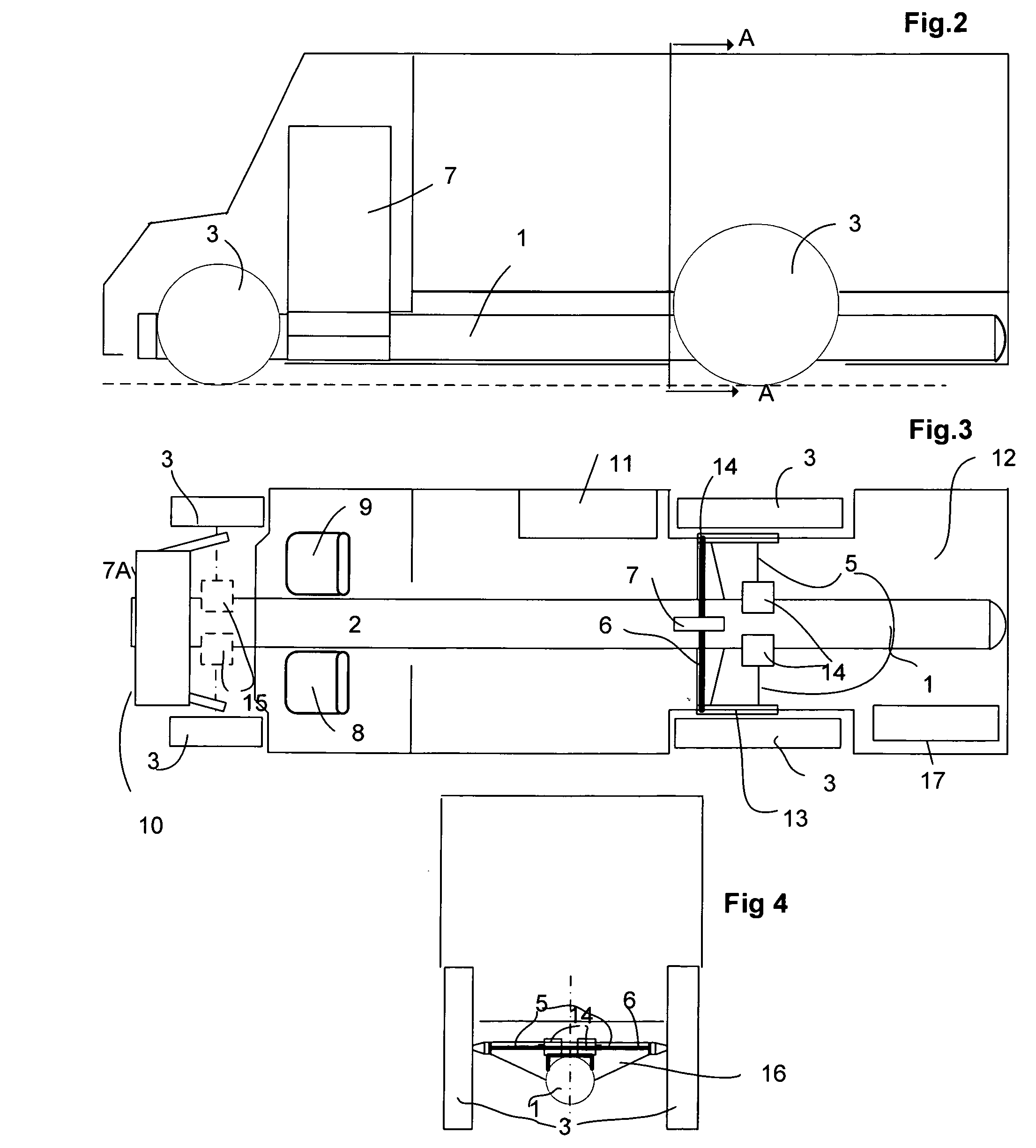
[0023]The preferred embodiment of the present invention is contained in FIG. 1. FIGS. 2, 3 and 4 there are just a description of a vehicle sample application of the preferred embodiment of the system on a commercial Van, UPS type.
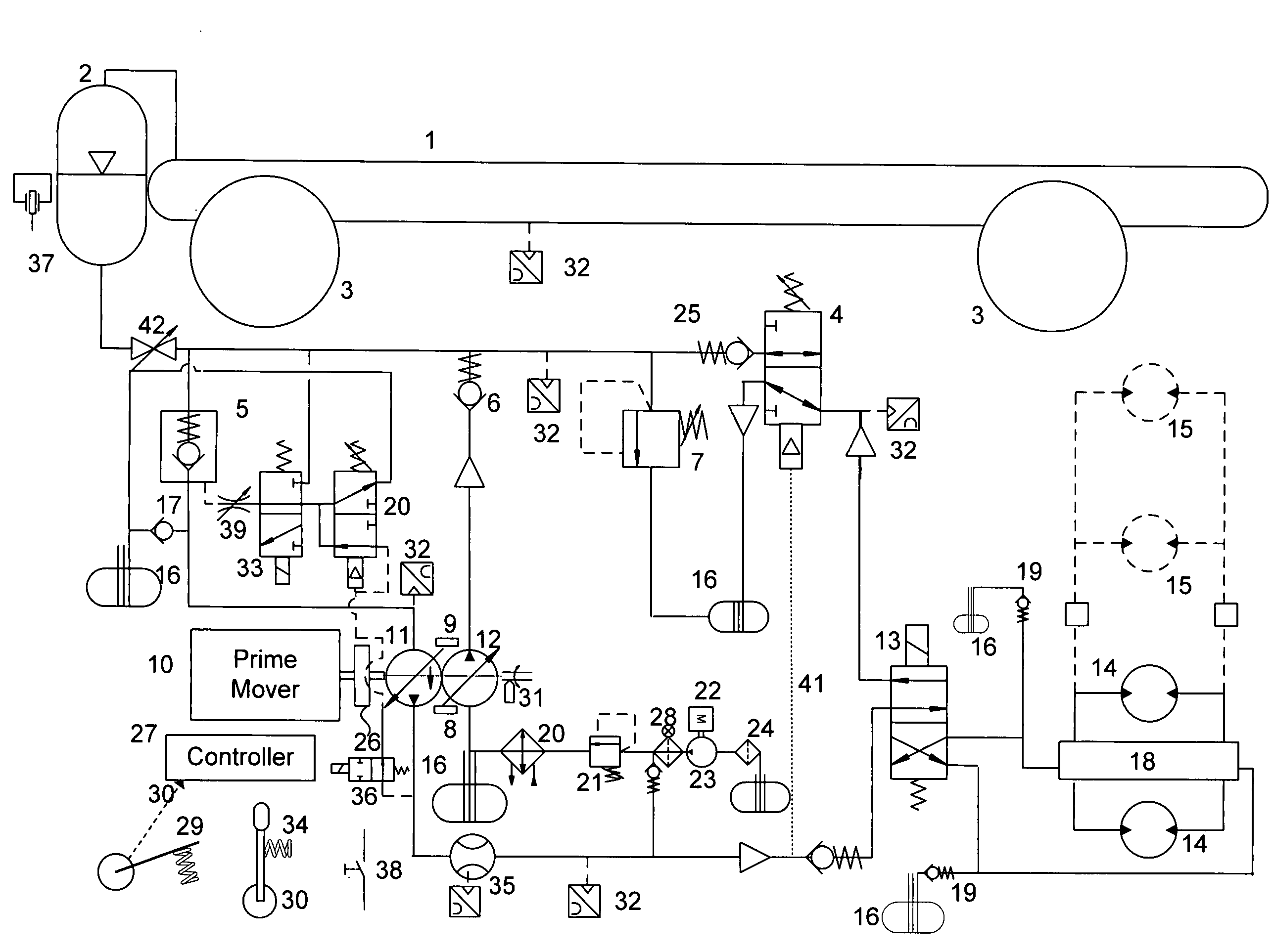
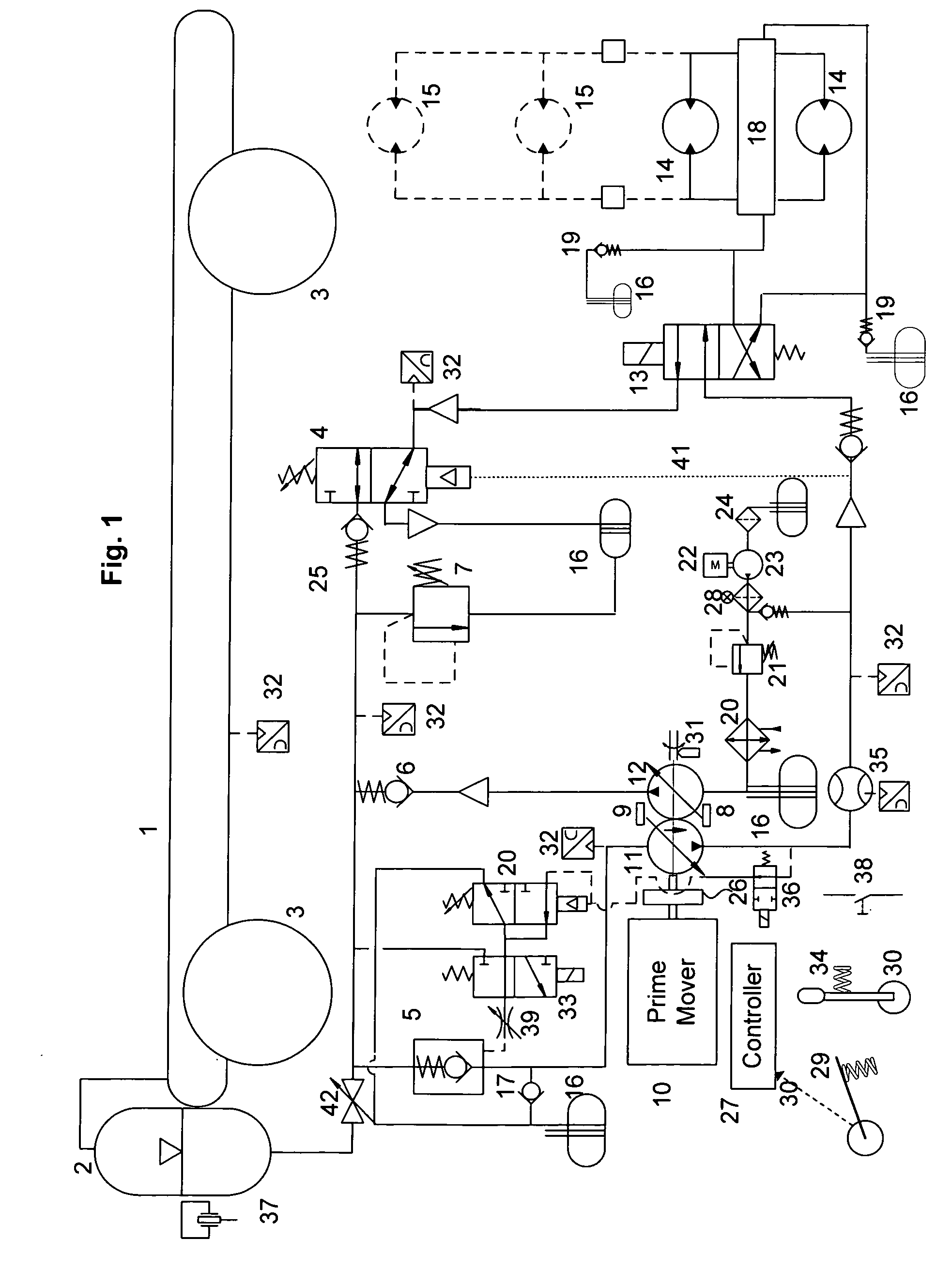
[0024]FIG. 1 depicts the preferred embodiment of the hydraulic circuit, indicating schematically an accumulator 1, the gas container, which at the same time, is the chassis of the vehicle. The oil / gas accumulator 2 could be separated from accumulators or could be installed inside accumulator 1.
[0025]The prime mover 10 is connected via a unidirectional coupling 26 to a special unidirectional variable power integrator 11 and in the same shaft, to a unidirectional variable flow pump 12. This unidirectional coupling is required to allow for the operation of the system when the prime mover is not running. Pump 11 is controlled by servo valve 9 and pump 12 is controlled by servo valve 8. Both servo valves receive the proper signals from the controller 27. The acc...
PUM
Abstract
A new hybridhydraulic drive system for all types of terrestrial vehicles, including vehicles running on rails, using as prime mover any of the ICE (internal combustion engine) available or turbine, battery propulsion, electric motors, fuel cells, etc. One special variable hydraulic pump connected to the prime mover acts as a “power integrator”, receiving hydraulic power from the accumulator and mechanical power from the prime mover, to supply the desired flow and pressure to the hydraulic motors during operation. A second variable pump, reloads the accumulator with the remnant power available, if any, during the whole cycle. The accumulator is quite large and it is also used as the chassis for all terrestrial vehicles. The braking energy is returned to the accumulator. The whole vehicle is controlled by electronics, and in one embodiment, using only one joystick or pedal to control speed, direction, acceleration, braking and in some cases including steering.
Application Information
Patent Timeline
Application Date:The date an application was filed.
Publication Date:The date a patent or application was officially published.
First Publication Date:The earliest publication date of a patent with the same application number.
Issue Date:Publication date of the patent grant document.
PCT Entry Date:The Entry date of PCT National Phase.
Estimated Expiry Date:The statutory expiry date of a patent right according to the Patent Law, and it is the longest term of protection that the patent right can achieve without the termination of the patent right due to other reasons(Term extension factor has been taken into account ).
Invalid Date:Actual expiry date is based on effective date or publication date of legal transaction data of invalid patent.
Patent Type & AuthorityApplications(United States)

