Low Noise Binary-Coded Gain Amplifier and Method for Time-Gain Compensation in Medical Ultrasound Imaging

a binary-coded gain amplifier and ultrasound imaging technology, applied in the field of low-noise amplifiers, can solve the problems of signal-to-noise ratio (snr) degradation in doppler modalities, use of resistors in programmable gain amplifiers of this kind, and increase the gain of receiving channels

Inactive Publication Date: 2010-05-20
MICROCHIP TECH INC
View PDF8 Cites 18 Cited by
  • Summary
  • Abstract
  • Description
  • Claims
  • Application Information

AI Technical Summary

Benefits of technology

[0033]In the present invention, a digitally controllable variable gain amplifier circuit comprises a differential voltage-mode input terminal for receiving a differential pair of input signals and a plurality of switchable voltage-to-current (V-to-I) converters. These converters receive said pair of input signals in parallel. Each of the V-to-I converter also receives a control signal turning the converter ON and OFF, and provides a differential pair of output current signals. A differential transimpedance amplifier receives the plurality of output signals from the plurality of switchable V-to-I converters and provides a differential pair of voltage signals in response thereto. A look-up-table (LUT) stores a plurality of signals which are supplied to the plurality of switchable V-to-I converters as control signals therefor.
[0034]The present invention also relates to a method of compensating the attenuation of echo signals produced in an ultrasound imaging system from different depths by progressively increasing the gain of a receive channel during reception. The echoes returned from the tissue are applied to a digitally programmable transconductor comprising a plurality of N V-to-I converters adapted to be turned ON and OFF. When ON, the transconductance of a converter is binary weighted with respect to the transconductances of other ones of the plurality V-to-I converters. The current outputs of the plurality of said V-to-I converters are summed and supplied to a transconductance amplifier which converts the current into a voltage signal. The state (ON / OFF) of each V-to-I converter is controlled by a logical signal supplied from a look-up-table.

Problems solved by technology

Unfortunately, use of these resistors induces an additional noise.
Consequently, a programmable gain amplifier of this kind contributes more noise than the basic differential amplifier without emitter resistors.
As explained below, a problem with the VGA of FIG. 1 is the signal-to-noise ratio (SNR) degradation in Doppler modalities.
However, since the circuitry is noticeably complex, it would result in high manufacturing cost and substantial power consumption.
Consequently, this scheme of gain setting is rather coarse.
However, the subsequent analysis shows that the proposed technique comes to only adding few predetermined gain values.

Method used


Image

  • Low Noise Binary-Coded Gain Amplifier and Method for Time-Gain Compensation in Medical Ultrasound Imaging
  • Low Noise Binary-Coded Gain Amplifier and Method for Time-Gain Compensation in Medical Ultrasound Imaging
  • Low Noise Binary-Coded Gain Amplifier and Method for Time-Gain Compensation in Medical Ultrasound Imaging

Examples


Embodiment Construction

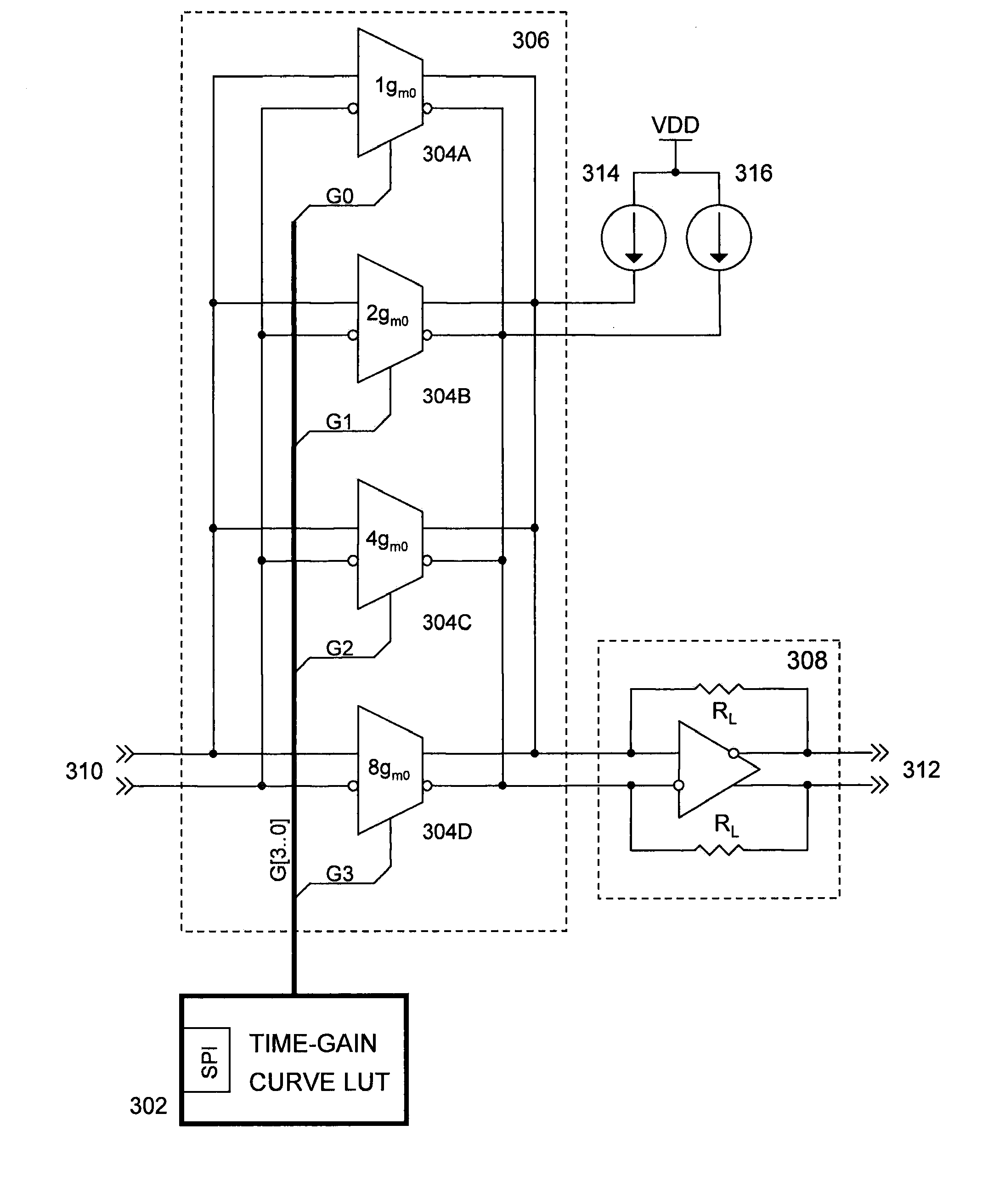
[0042]The following sections will discuss an improved low noise VGA, which gain is directly controlled by an external N-bit-wide word allowing to obtain 2N−1 gain levels within a given gain range. A description of the present invention is given with reference to FIGS. 3-6.

[0043]FIG. 3 is a functional block diagram showing the relationship between the elements of the VGA of the present invention. Referring to the diagram, the VGA comprises a differential input port 310 for receiving signals generated e.g. by a transducer, such as a piezoelectric transducer of an ultrasound medical imaging device, two identical current sources 314 and 316, a differential programmable transconductor 306 loaded by said current sources and connected to a differential transimpedance amplifier (that is, a current-to-voltage converter) 308 having a differential output port 312, and a look-up-table (LUT) 302 for storing a set of time-gain curves.

[0044]As it will be shown later in detail, the programmable tra...


PUM


Abstract

A low noise variable gain amplifier and method for processing received signals in an ultrasound medical imaging system is disclosed. Unlike solutions known from the prior art, the signals are amplified by a binary-coded gain amplifier having its amplification factor progressively increased during the penetration of the transmitted pulse into a patient's body. This allows enhancing both the system dynamic range and Signal to Noise Ratio.

Description

RELATED APPLICATIONS[0001]This patent application claims the benefit of U.S. Provisional Patent Application having a Ser. No. 61 / 199,725, filed Nov. 19, 2008 in the name of Lazar A. Shifrin, and entitled “Medical Ultrasound System Having Digital Method and Circuitry for Front-End Gain Control”, whose disclosure is incorporated herein by reference in its entirety.BACKGROUND OF THE INVENTION[0002]1. Field of the Invention[0003]This invention relates generally to low noise amplifiers having operatively digitally controllable gain. Specifically, the invention relates to digitally controllable variable-gain amplifiers and more particularly to such amplifiers used in ultrasound imaging.[0004]2. Description of the Related Art[0005]Variable-gain amplifiers (VGA) have been used for many years in a wide variety of applications including communication and ultrasound imaging.[0006]In communication, a transmitter transmits a radio frequency modulated signal over a transmission channel to a recei...

Claims


Application Information

Patent Timeline
Patent Type & Authority Applications(United States)
IPC IPC(8): H03F3/45
CPCH03F3/45183
Inventor SHIFRIN, LAZAR A.
Owner MICROCHIP TECH INC
Why Eureka
Try Eureka