Reinforced panel

Inactive Publication Date: 2010-05-27
AIRBUS OPERATIONS LTD
View PDF8 Cites 10 Cited by
  • Summary
  • Abstract
  • Description
  • Claims
  • Application Information

AI Technical Summary

Benefits of technology

[0017]The strain actuators may be at least partially embedded in the skin. This may

Problems solved by technology

Despite their high level of performance in specific areas, such as weight, durability and through-life costs, composites are not widely accepted in primary structures.
This is mostly due to a reduced understanding of the failure mechanisms and of their behaviour when damaged.
This widespread lack of knowledge and know-how often leads to over sized structures, which are in contrast with the lightweight philosophy characterizing all the new

Method used


Image

  • Reinforced panel
  • Reinforced panel
  • Reinforced panel

Examples


Embodiment Construction

)

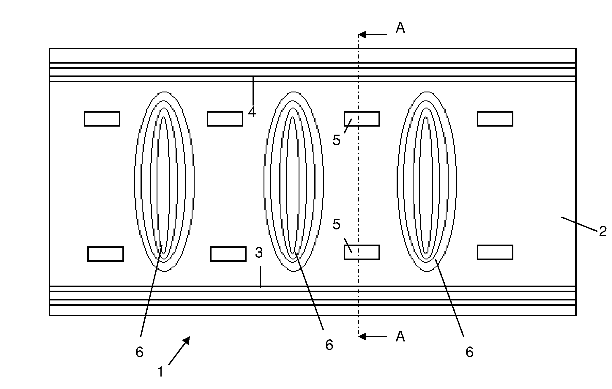
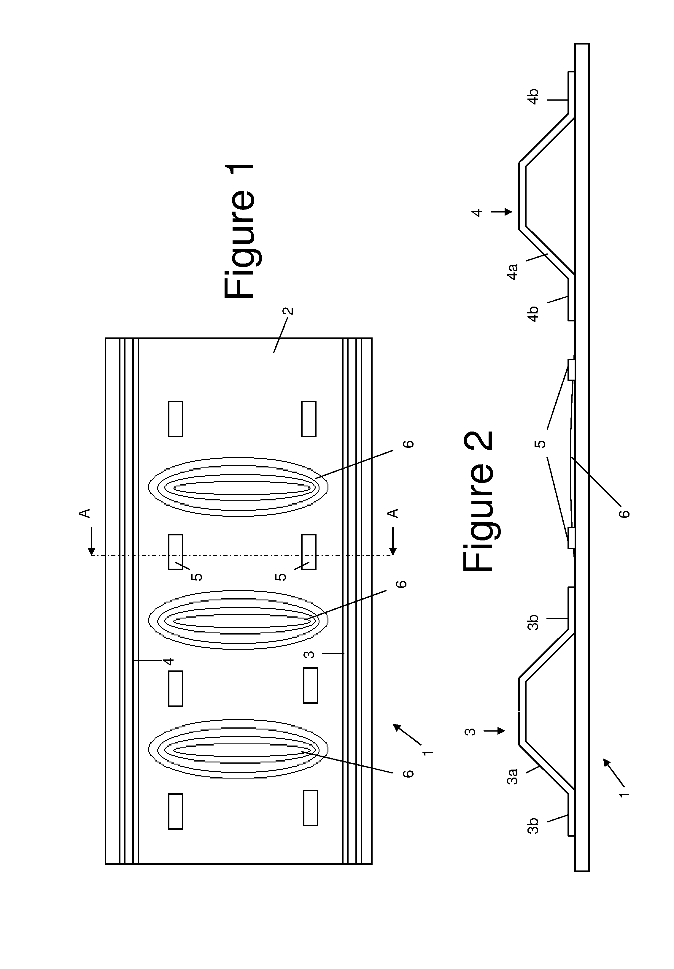
[0030]A portion of a reinforced panel 1 is shown in FIGS. 1 and 2. The panel may form, for example, the skin of an aircraft wing or fuselage. The panel comprises a composite skin 2; a plurality of composite stringers 3,4 co-cured to the skin; and a two-dimensional array of piezoelectric strain actuators 5 positioned between the stringers. In the case of an aircraft wing, the stringers run in a span-wise direction from the root of the wing towards its tip.

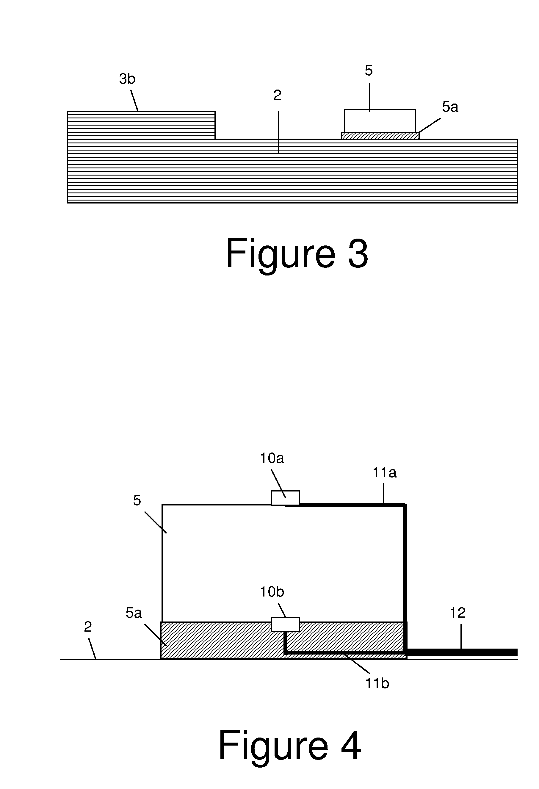
[0031]FIG. 1 shows only a small portion of the panel, which extends further in both the horizontal and vertical directions. As shown in FIG. 2, each stringer comprises a web 3a,4a extending from the skin and a pair of flanges 3b,4b which are bonded to the skin 2.

[0032]Each strain actuator 5 is bonded to the skin 1 by an adhesive layer 5a shown in FIGS. 3 and 4. A pair of electrodes 10a and 10b are bonded to the upper and lower faces of the actuator. Each electrode is connected to a respective control line 11a,11b and the control li...


PUM


Abstract

A reinforced panel (1) comprising: a composite skin (2); a plurality of stringers (3, 4) bonded to the skin; and one or more strain actuators (5), each positioned between an adjacent pair of stringers. A load is applied to the panel in the plane of the skin, and a local strain is applied to the skin by the strain actuators when the compressive load exceeds a predetermined threshold. This causes the skin to buckle and reduce interface stresses between the skin and the stringers.

Description

FIELD OF THE INVENTION[0001]The present invention relates to a reinforced panel comprising a composite skin; and a plurality of stringers bonded to the skin. The invention also relates to a method of buckling such a reinforced panel.BACKGROUND OF THE INVENTION[0002]Despite their high level of performance in specific areas, such as weight, durability and through-life costs, composites are not widely accepted in primary structures. This is mostly due to a reduced understanding of the failure mechanisms and of their behaviour when damaged. This widespread lack of knowledge and know-how often leads to over sized structures, which are in contrast with the lightweight philosophy characterizing all the new design solutions.[0003]Buckling still represents one of the most controversial issues of reinforced panel design. It is well known that composite stiffened panels can carry in plane loads higher than the buckling load without any failure. Unfortunately, the complexity and expensiveness o...

Claims


Application Information

Patent Timeline
IPC IPC(8): G01M19/00G01M99/00
CPCB64C1/12B64C3/48B64C3/26
Inventor COSENTINO, ENZO
Owner AIRBUS OPERATIONS LTD
Why Eureka
Try Eureka