
Conveyor Roll And Process For Its Assembly

a technology of conveyor rolls and end caps, applied in the direction of packaging, manufacturing tools, couplings, etc., can solve the problems of end cap slipping and the diminishing power of the tolerance ring, and achieve the effect of preventing eccentric rotation of the spool and efficient torque transfer

Active Publication Date: 2010-05-27
VESUVIUS USA CORP
View PDF12 Cites 11 Cited by
  • Summary
  • Abstract
  • Description
  • Claims
  • Application Information

AI Technical Summary

Benefits of technology

[0009]Tolerance rings are known from U.S. Pat. No. 3,061,386. They are described as made from resilient metal and have a plurality of circumferentially arranged corrugations of defined height and pitch, with both the height and pitch of the corrugations significantly lower than the diameter of the ring. Typically, the pitch is lower than 10% of the diameter and preferably lower than 8% of the diameter. Typically, the height is lower than 5% of the diameter and preferably lower than 3% of the diameter. U.S. Pat. No. 3,142,887 indicates a method of making such tolerance rings. This design is very particular and can be opposed to an helicoïdally wound flat sided coil. Due to this particular design, the tolerance ring shows very significant flexibility. Numerous variants of the tolerance rings have been described in the art (variable heights, pitches, multiple rows of corrugations aligned or offset, . . . ) and are sold by various companies. In principle all these kinds of tolerance rings can be used. It is preferable to have an open tolerance ring having a length lower than the internal circumference of the end cap since when the roll neck is introduced into the end cap provided with the tolerance ring, this must be able to accommodate the small dimensional variations that might occur during manufacturing of the spool or end cap. It might be advantageous to have a second open tolerance ring parallel to the first one but with their opening offset so as to improve the coaxiality of the spool in the end cap. It is also very advantageous to have a relatively limited pitch (less than 20 mm between two wave “highs”) to obtain an increased rigidity.
[0010]It is preferred to have the corrugations oriented inwardly so that in case of slippage, this will occur only with respect to the “tolerance ring-end cap” couple and will not damage the surface of the spool.
[0011]According to an advantageous embodiment of the invention, at least one of the tolerance rings is provided with at least one tab while, in parallel, the corresponding end of the ceramic spool is provided with one or more notch(es) adapted to receive the tab(s) of the tolerance ring. Such an arrangement will prevent relative movement in one axial direction between the tolerance ring and the spool. Since it is preferable to prevent the withdrawal of the spool from the tolerance ring especially during a temporary overheat (i.e., when the pressure exerted on the spool by the tolerance ring is minimal), it is preferable to have the tab(s) oriented so that the end of the tab will cooperate with the wall of the notch the closest to the end of the spool. Thereby, the spool can only move slightly towards its end and abut the bottom of the end cap. If such tolerance rings provided with these advantageous tabs are provided on both sides of the spool, all relative movements of the spool are prevented.
[0012]According to another embodiment, the tolerance ring is provided with at least two tabs and one tab has an orientation opposite to at least another tab. Thereby, all relative movements of the spool with respect to a single tolerance ring are prevented.
[0013]As indicated above, the end cap has an inner circumference to receive a tolerance ring and one end of a spool. Advantageously, the end cap is provided with a step to limit relative movements between the tolerance ring and the end cap. According to a particularly preferred embodiment, the end cap is provided with a groove adapted to receive the tolerance ring. Thereby all axial movements of the tolerance ring with respect to the end cap are prevented even in case of a temporary overheat. It is especially advantageous to combine the presence of tabs on the tolerance ring with the groove in the end cap to avoid any relative movement of the spool with respect to the end cap during a temporary overheat.

Problems solved by technology

Thereby, the fastening power of the tolerance ring will diminish and the spool will start slipping in the end cap.

Method used


Image

  • Conveyor Roll And Process For Its Assembly
  • Conveyor Roll And Process For Its Assembly
  • Conveyor Roll And Process For Its Assembly

Examples


Embodiment Construction

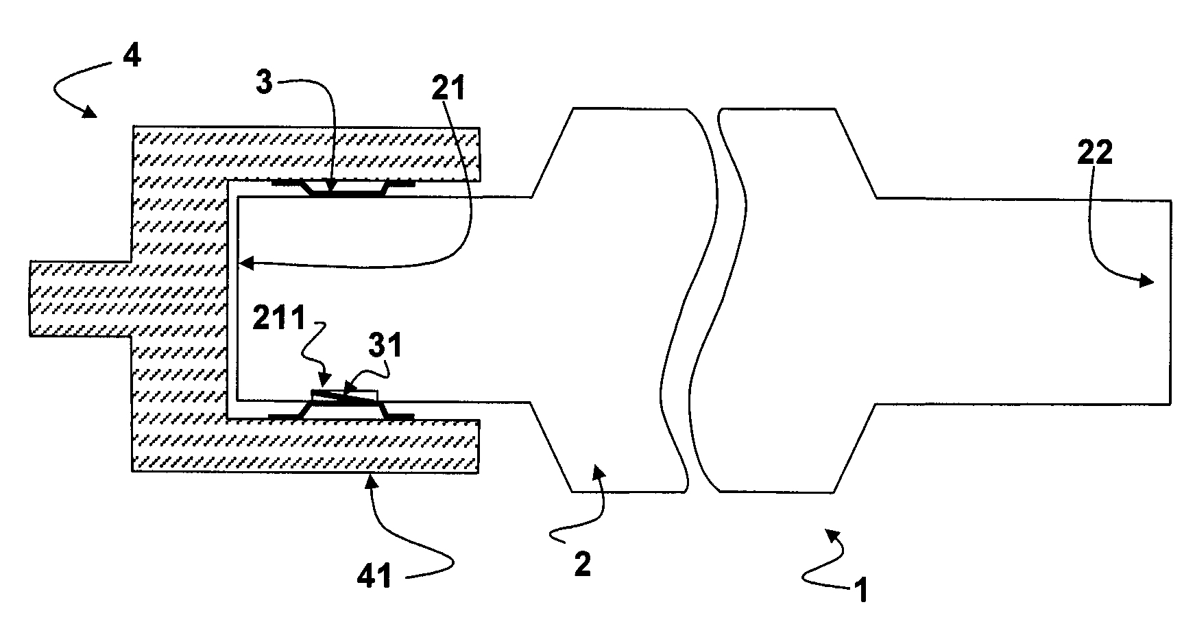
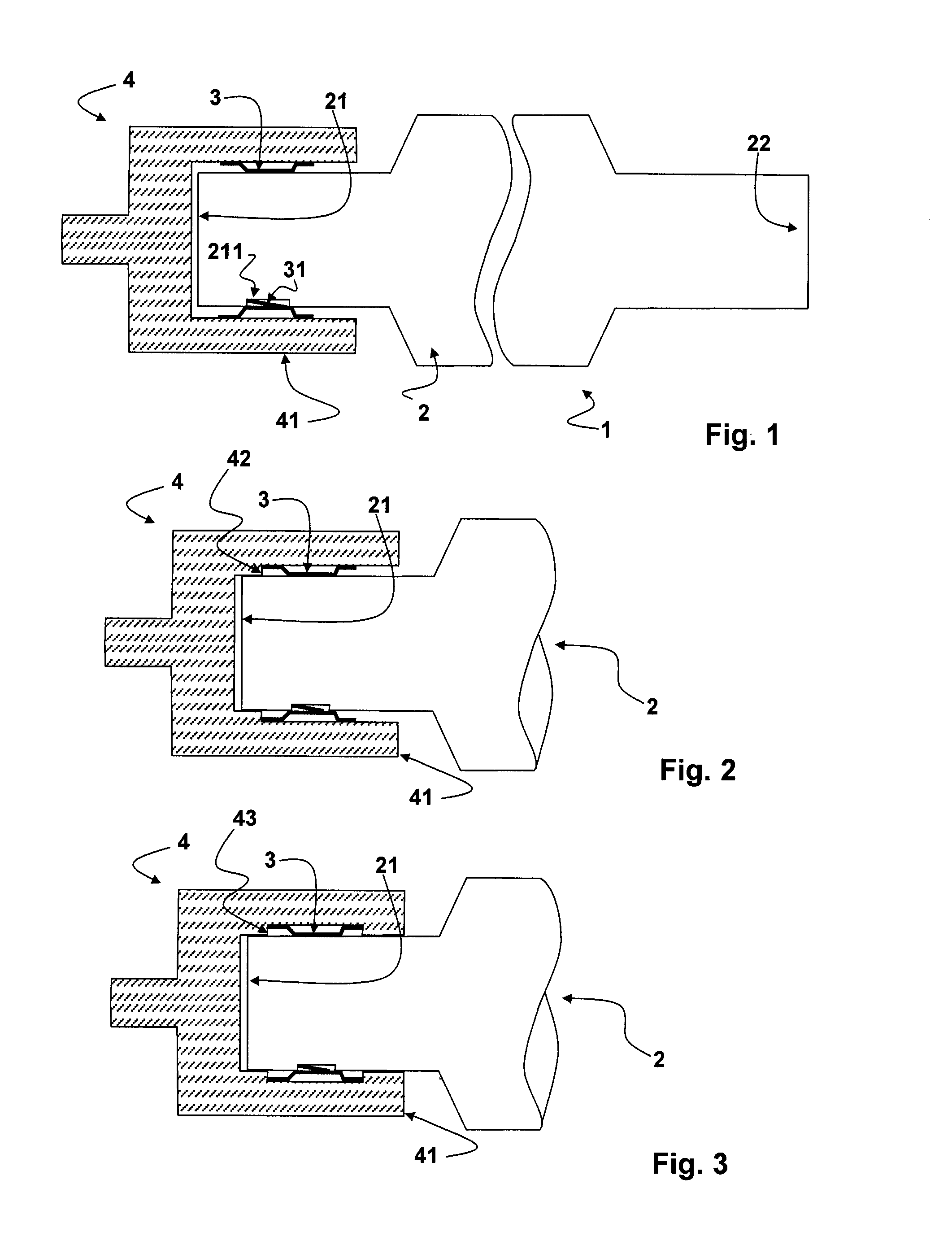
[0021]On these figures, 1 depicts generally a conveyor roll comprising a ceramic spool 2 having two ends 21 and 22. An end cap 4 comprising a ferrule 41 is arranged on both ends of the spool 2 (only the end cap provided at the end 21 is shown on FIG. 1). A tolerance ring 3 is inserted in the end cap 4. The end cap 4 has a regular inner surface on FIG. 1, while FIGS. 2 and 3 show respectively an end cap 4 provided with a step 42 or a groove 43 for restraining the movements of the tolerance ring 3 in the end cap.

[0022]The tolerance ring can be provided with a tab 31 cooperating with the wall of a notch provided in the end of the ceramic spool 21. On FIGS. 1 to 3, the tab 31 cooperates with the wall of the notch the closest to end 21 of the spool 2.

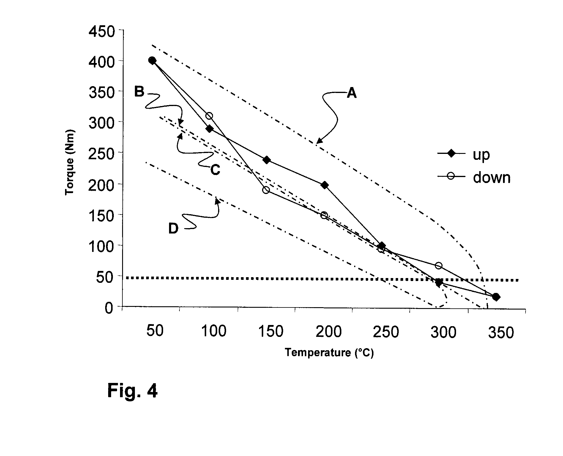
[0023]Trials have been performed with a conveyor roll according to FIG. 2 so as to demonstrate the possibility of the conveyor roll to resist a temporary overheat and to recover its normal operating conditions when the temperature returns ba...


PUM

PropertyMeasurementUnit
temperatureaaaaaaaaaa
lengthaaaaaaaaaa

Abstract

Conveyor rolls used in high temperature applications, and an end cap assembly for such rolls. The conveyor roll comprises a ceramic spool, an end cap and a tolerance ring. The end cap contains a metal ferrule and has an internal circumference adapted to fit over an end of the ceramic spool. A tolerance ring is interposed between each end of the ceramic spool and the end cap. The tolerance ring is composed of resilient metal having a plurality of circumferentially arranged corrugations. The conveyor roll can resist temporary overheating or blockage without damage.

Description

FIELD OF THE INVENTION[0001]The present invention relates to conveyor rolls used in high temperature applications, and more particularly concerns an improved end cap assembly for such rolls.BACKGROUND OF THE INVENTION[0002]A conveyor roll used in high temperature applications may comprise a ceramic spool having metal end caps. Typically, the ceramic spool comprises fused silica. The end caps permit facile mounting to a bearing or drive wheel. For example, in glass tempering applications, the ceramic spool supports glass sheet, and the end caps permit mechanical coupling to the drive mechanism. The end caps should securely adhere to the spool, thereby permitting the spool to rotate at the desired speed. Eccentric rotation is generally undesirable, as this would create an uneven support surface for the glass sheet.[0003]The different thermal expansions of the ceramic spool and the metal end caps makes securely fastening the end caps to the spool difficult and can create eccentric rota...

Claims


Application Information

Patent Timeline
Patent Type & Authority Applications(United States)
IPC IPC(8): B65G13/00B23P11/00
CPCB65G39/00B65G39/02Y10T29/49826F16C13/00B65G2207/22F16D1/0835
Inventor GAUTIER, DAVIDFLAMME, ARNAUD
Owner VESUVIUS USA CORP
Learn More