

Information recording/reproducing device
a recording/reproducing device and information technology, applied in the field of information recording/reproducing devices, can solve problems such as recording media depression, and achieve the effect of low power consumption and high recording density
- Summary
- Abstract
- Description
- Claims
- Application Information
AI Technical Summary
Benefits of technology
Problems solved by technology
Method used
Image

Examples
first example
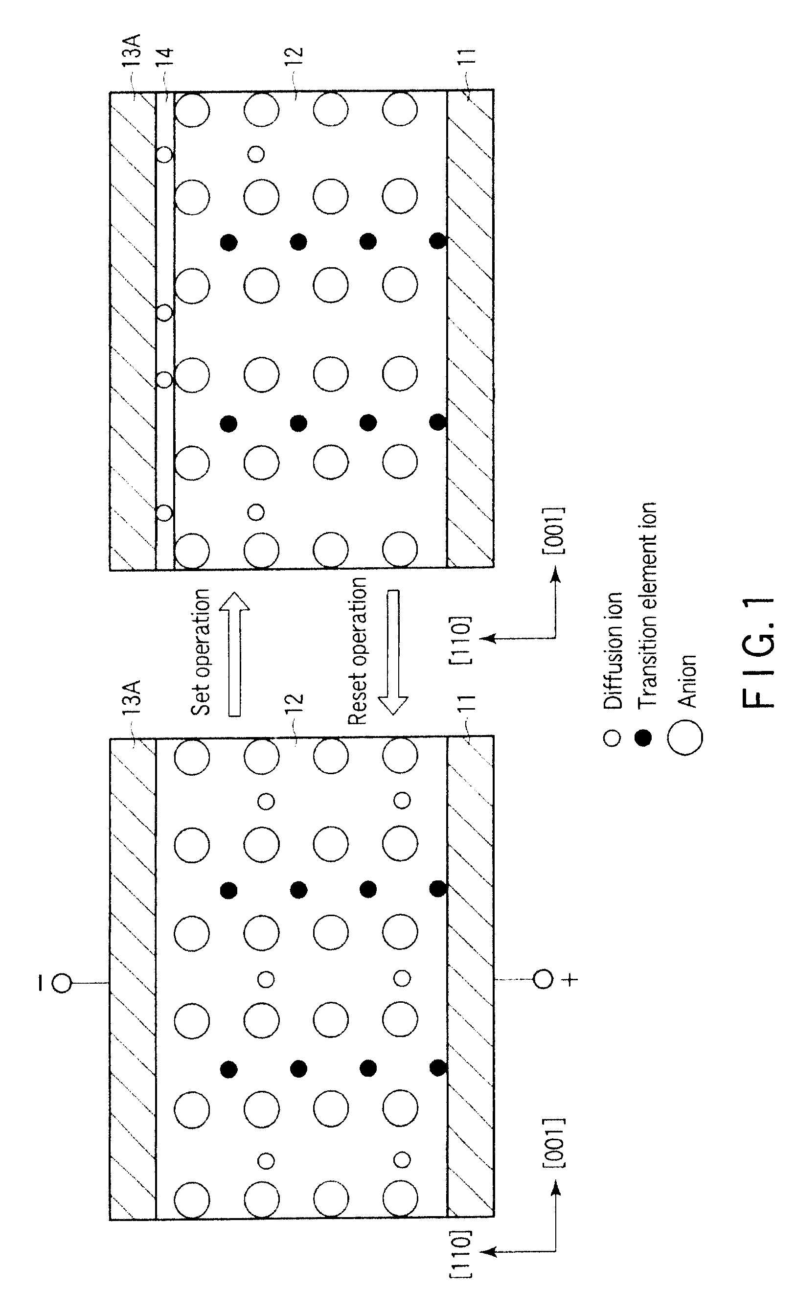
[0229]The materials of FIG. 1 are used for the recording layer in the first example.
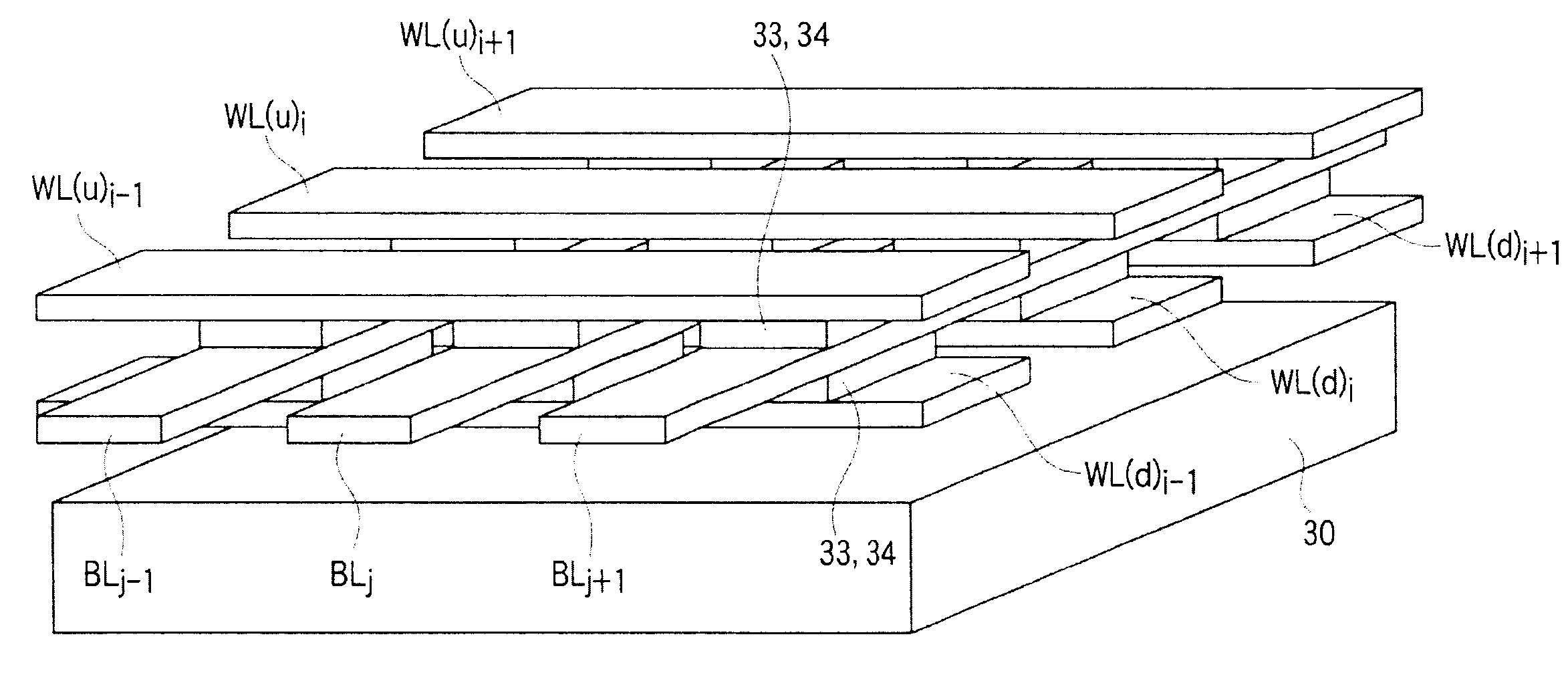
[0230]Since it is adequate for the recording (set operation) to apply the voltage to the selected memory cell 33 followed by generating potential gradients inside the memory cell 33 to cause current pulses to flow therein, for instance, there is prepared a state where the electric potential of the word line WLi is relatively lower than the electric potential of the bit line BLj. It is only necessary to provide a negative potential to the word line WLi when the bit line BLj has the fixed potential, for instance, ground potential.
[0231]At this time, in the selected memory cell 33 surrounded by the dotted line A, part of diffusion ions moves to the word line (cathode) WLi side, and cations inside the crystal relatively decrease to anions. Further, diffusion ions having moved to the word line WLi side separate out as metal while receiving the electrons from the word line WLi.
[0232]In the selected memory ...
second example
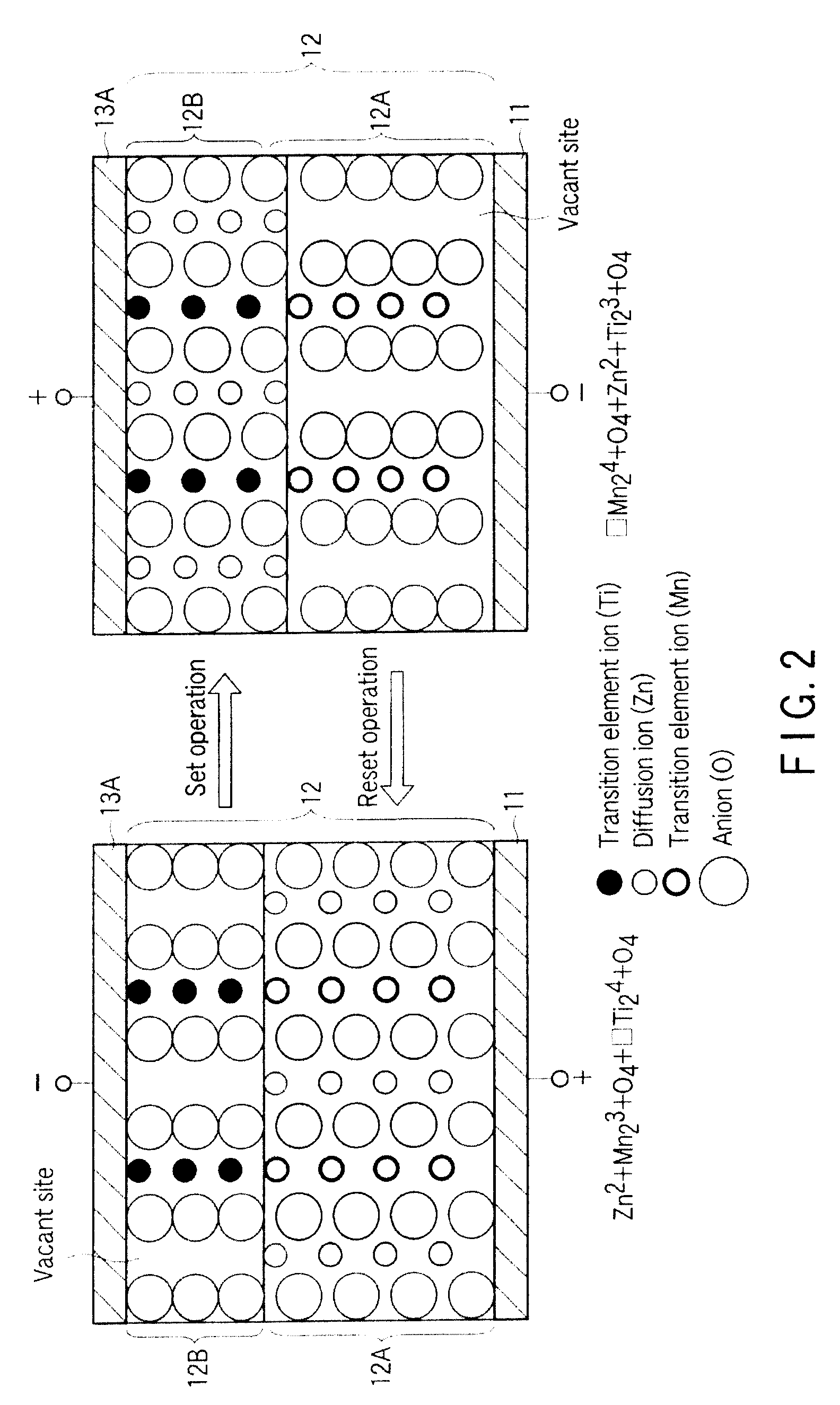
[0239]The materials of FIG. 2 are used for the recording layer in the second example.
[0240]Since it is adequate for the recording (set operation) to apply the voltage to the selected memory cell 33 followed by generating potential gradients inside the memory cell 33 to cause current pulses to flow therein, for instance, there is prepared a state where the electric potential of the word line WLi is relatively lower than the electric potential of the bit line BLj. It is only necessary to provide a negative potential to the word line WLi when the bit line BLj has the fixed potential, for instance, ground potential.
[0241]At this time, in the selected memory cell 33 surrounded by the dotted line A, part of diffusion ions inside the first chemical compound moves to the vacant site of the second chemical compound. For this reason, the valence of transition element ions inside the first chemical compound increases, and the valence of transition element ions inside the second chemical compou...
experimental example
5. Experimental Example
[0274]Experimental examples in which some samples are prepared to evaluate a resistance ratio of the reset state (erasing state) and the set state (writing state) will be described.
[0275]The recording medium having the structure of FIG. 6 is used as the sample.
[0276]A probe pair in which a diameter of a leading end is steepled to 10 nm or less is used in the evaluation.
[0277]One of the probes is brought into contact with the protection layer 13B and grounded. The other probe is brought into contact with the lower electrode layer 21 to perform the writing / erasing. For example, the writing is performed by applying the pulse having the voltage of 1V and the width of 10 ns to the recording layer 22. For example, the erasing is performed by applying the pulse having the voltage of 0.2V and the width of 100 ns to the recording layer 22.
[0278]For example, the reading is performed using the probe pair between the writing and the erasing. In the reading, the pulse havi...
PUM
 Abstract
Description
Claims
Application Information