Projection image display device and projection optical system

Active Publication Date: 2010-05-27
SONY CORP
View PDF2 Cites 40 Cited by
  • Summary
  • Abstract
  • Description
  • Claims
  • Application Information

AI Technical Summary

Benefits of technology

[0023]In the projection image display device having the above-described structure, by moving at least one optical component of the first optical system substantially perpendicularly to the optical axis, the secondary image surface on the screen is moved. That is, by moving the at least one optical component of the first optical system, the screen shift function is realized. Therefore, compared to, for example, the case in which the entire projection optical system is moved or the case in which the image modulating element is moved, the number of components to be moved is reduced and the display device is smaller, so that it is possibl

Problems solved by technology

However, the above-described related arts have the following problems.
Therefore, as a mechanism for realizing the screen shift function, it is necessary to use a large mechanism that can withstand the weight of the entire projection optical system, as a result of which costs may be considerably increased.
In the structure disclosed in Pate

Method used


Image

  • Projection image display device and projection optical system
  • Projection image display device and projection optical system
  • Projection image display device and projection optical system

Examples


first embodiment

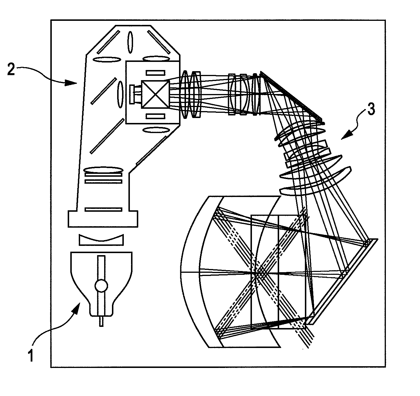
[0137]FIG. 8 is a ray diagram schematically showing an exemplary structure of a projection optical system according to a first embodiment. FIG. 8 shows an optical path when a distance is a standard projection distance.

[0138]As shown in FIG. 8, the projection optical system 3 includes a first optical system L1 having a positive refractive power and a second optical system L2 having a concave reflecting surface.

[0139]The first optical system L1 has a common optical axis at which all optical components of the first optical system L1 have rotationally symmetric surfaces.

[0140]The second optical system L2 is formed by a rotationally symmetric aspherical surface, and has the optical axis in common with the first optical system L1.

[0141]By including the first optical system L1 and the second optical system L2, the projection optical system 3 is formed so as to perform extended projection from a tele-side primary image surface to a wide-side secondary image surface. That is, the image infor...

second embodiment

[0187]FIG. 20 schematically illustrates an exemplary structure of a projection optical system according to a second embodiment. In the illustration, an optical path when the distance is a standard projection distance is shown.

[0188]FIG. 21 illustrates an exemplary structure of the main portion of the projection optical system according to the second embodiment. In the illustration, lenses of a first optical system L1 when short distance projection is performed are shown in cross section.

[0189]As in the illustration, in a projection optical system 3 according to the second embodiment, an optical component that is moved for realizing the screen shift function SF is different from those in the first embodiment. That is, the screen shift function SF is realized by moving an optical component of an 11th optical system L11 instead of the entire 11th optical system L11.

[0190]In addition, in the projection optical system 3 according to the second embodiment, an optical component that is mov...

third embodiment

[0204]FIG. 31 schematically illustrates an exemplary structure of a projection optical system according to a third embodiment. In the illustration, an optical path when the distance is a standard projection distance is shown.

[0205]FIG. 32 illustrates an exemplary structure of the main portion of the projection optical system according to the third embodiment. In the illustration, lenses of a first optical system L1 when short distance projection is performed are shown in cross section.

[0206]As in the illustration, in a projection optical system 3 according to the third embodiment, as in the above-described first embodiment, the screen shift function SF is realized by moving the entire 11th optical system L11.

[0207]However, unlike the above-described first embodiment, the magnification changeover function MF is realized by moving two groups of the 11th optical system L11 along the optical axis.

[0208]The other structural features are the same as those of the first embodiment. Accordin...


PUM


Abstract

A projection image display device includes a light source; an illumination optical system that uniformly irradiates a surface of an image modulating element (primary image surface) with a light beam emitted from the light source; and a projection optical system that performs with respect to a screen (a secondary image surface) extended projection on image information provided at the primary image surface and modulated by the image modulating element. The projection optical system includes a first optical system having a positive refractive power, and a second optical system having a concave reflecting surface. The first optical system has a common optical axis at which all optical components of the first optical system have rotationally symmetric surfaces, and a screen shift function that causes the secondary image surface to be moved by moving at least one of the optical components of the first optical system substantially perpendicularly to the optical axis.

Description

BACKGROUND OF THE INVENTION[0001]1. Field of the Invention[0002]The present invention relates to a projection image display device that displays a projection image on a screen and a projection optical system used in the projection image display device.[0003]2. Description of the Related Art[0004]In recent years, as a projection image display device that displays a projection image on a screen, a projector device is widely available. In particular, in recent years, there is an increasing demand for a front-projection projector device of a super-wide angle type capable of performing a displaying operation on a large screen with a small projection space. A front-projection projector device of a super-wide angle type is used because projection can be performed on a large screen in a limited space by driving it in obliquely and at a wide angle with respect to the screen.[0005]However, if the projector device is, for example, a super-wide angle type in which a super-wide angle is approxim...

Claims


Application Information

Patent Timeline
IPC IPC(8): G03B5/04G03B21/28G02B27/18
CPCH04N9/3105H04N9/3197G03B21/28G03B5/04G02B17/0896
Inventor NISHIKAWA, JUN
Owner SONY CORP
Why Eureka
Try Eureka