
Electronic Package

a technology of electronic components and packaging, applied in the direction of electrical equipment, rigid plastic containers, screening casings, etc., can solve the problems of generating disruptive emi emissions, emi emissions can be disruptive, and emi emissions can produce disruptive signal nois

Active Publication Date: 2010-05-27
TELEDYNE FLIR LLC
View PDF26 Cites 17 Cited by
  • Summary
  • Abstract
  • Description
  • Claims
  • Application Information

AI Technical Summary

Problems solved by technology

It is a general problem that electronic devices and / or systems emit electromagnetic interference (“EMI”) over various spectral bandwidths and the EMI emissions can be disruptive to the operation of the electronic device or system itself, or to independent but locally operating electronic devices or systems.
In addition to EMI being generated by electrical components and motive electrical devices, current fluctuations along conductive pathways, e.g., through wires, bus bars, conductive traces, or the like leading to and from electrical components and motive electrical devices can also generate disruptive EMI emissions.
Generally, EMI emissions produce disruptive signal noise.
Radio frequency interference (“RFI”) bands, e.g., 50-1000 MHz, can be particularly disruptive to the operation of many devices by inducing disruptive radio signal noise into their otherwise noise-free signals.
In particular, the operation of radio communication devices such as radio and television broadcasting systems, cellular telephone systems, and wireless computer network computers, and the like, can be adversely affected by RFI emissions emitted by unrelated devices.
Additional problems are encountered when electronic devices and / or systems are used in harsh military or commercial environments.
For instance, exposure to moisture, such as salt water or fog, may lead to corrosion or ingress of fluids.
However, the reference does not disclose any means for protecting the exterior surface from corrosive materials, and the reference does not disclose masking any portion of the interior surface.
However, the reference does not disclose any means of protecting either the interior or exterior surface from corrosive materials, and the reference does not disclose masking any portion of the interior surface.
However, the references do not disclose any means of protecting either the interior or exterior surfaces from corrosive materials, and the references do not disclose masking any portion of the interior surface.
However, the reference does not disclose a means of protecting both the interior and exterior surfaces from corrosive materials.

Method used


Image

  • Electronic Package
  • Electronic Package
  • Electronic Package

Examples


Embodiment Construction

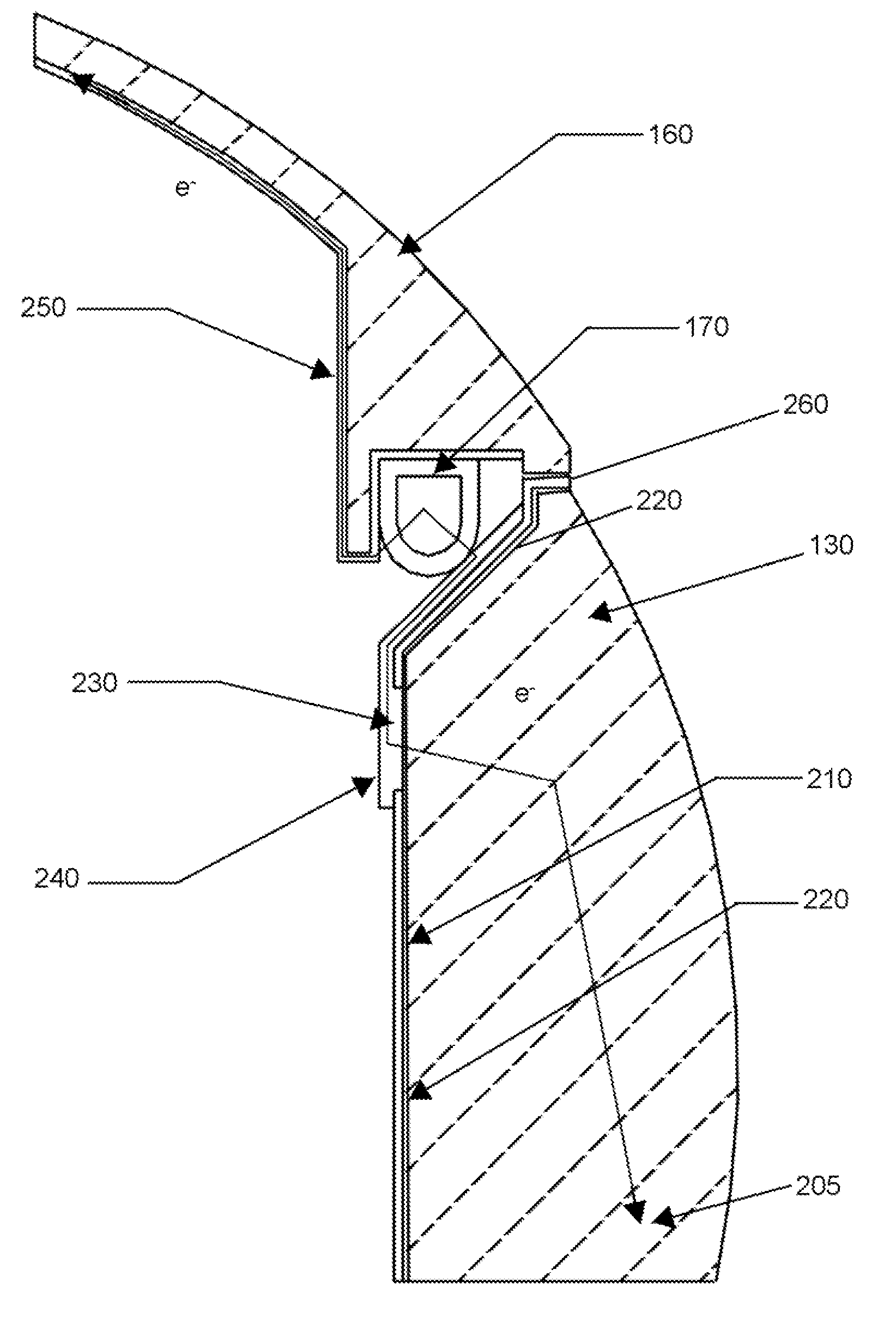
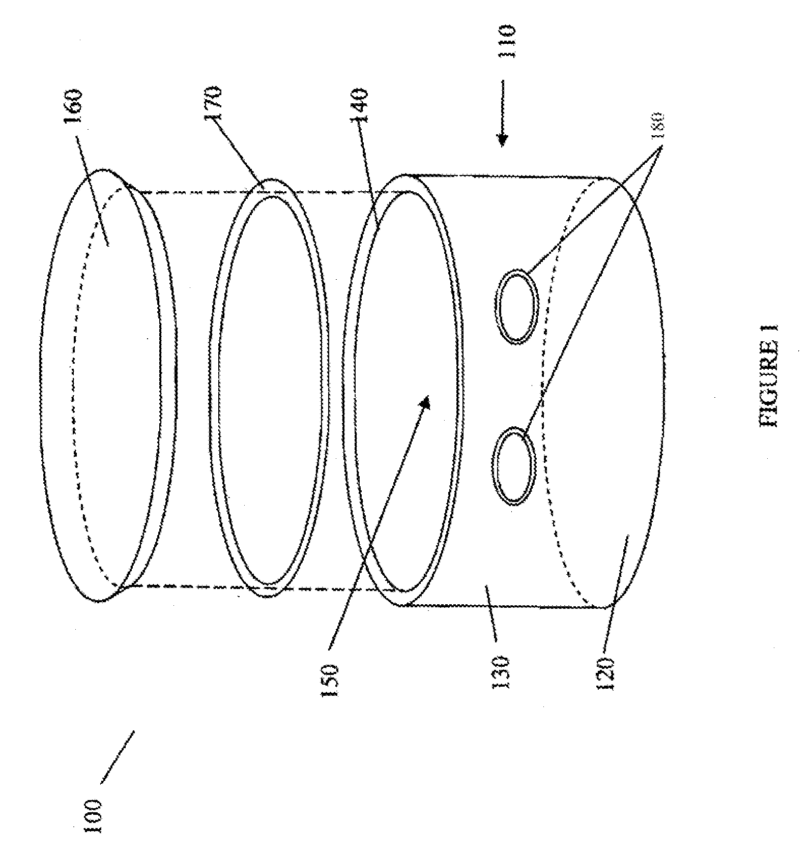
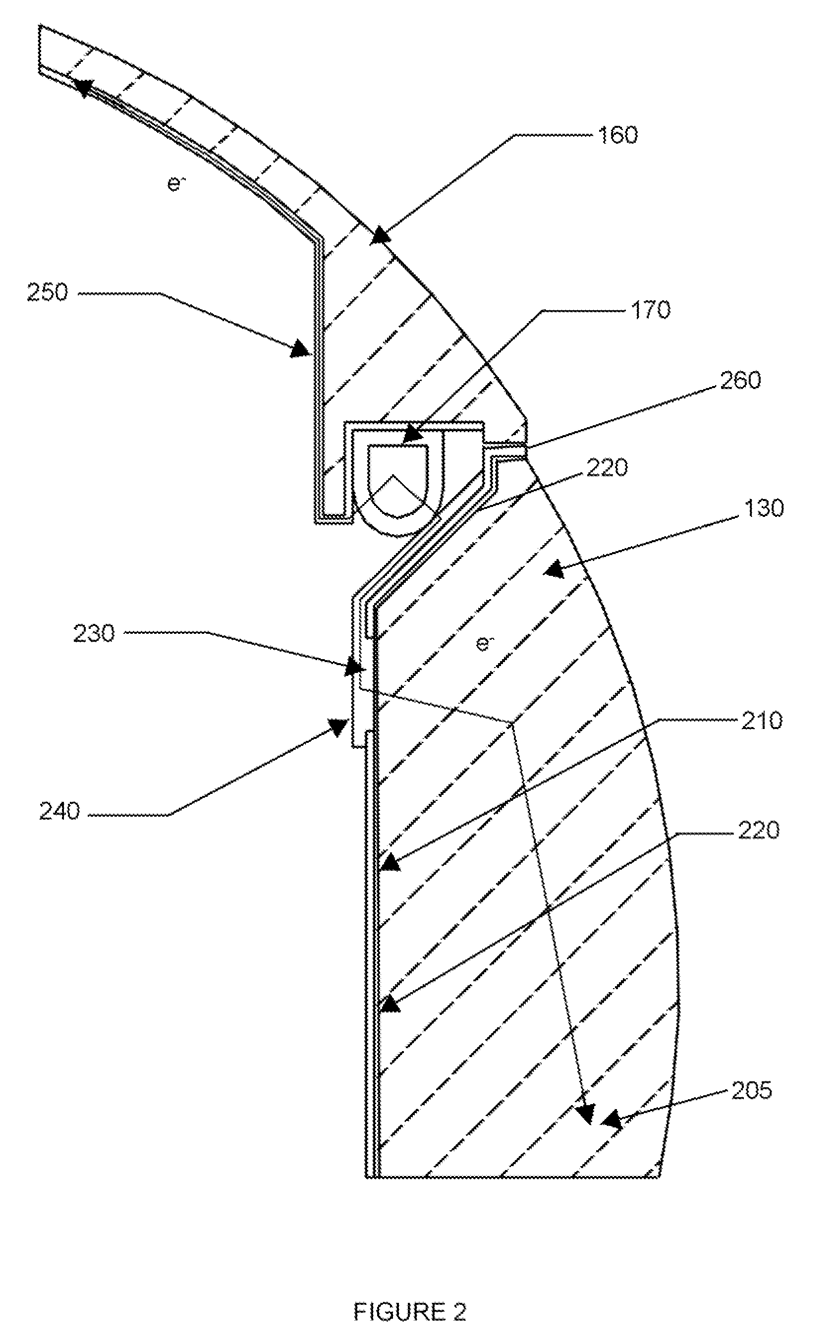
[0018]The present invention relates to a device package, such as an electronic system package, that is suitable for use in harsh military, industrial, or commercial environments. The package components, including a base enclosure and mating cover, comprise a series of interconnected electrically conductive materials, forming a tortuous electrically conductive path, that advantageously shield electromagnetic interference (“EMI”). The electrically conductive, EMI-shielding layers and other coated layers (e.g., insulative electrocoated paint layers) are smooth layers that provide corrosion resistance to the interior and exterior surfaces of the package. The device package is also designed such that its components form a water tight seal. Thus, innovatively, the package comprises a combination of components that synergistically shield electromagnetic interference, resist interior and exterior corrosion, and form a water tight seal.

[0019]FIG. 1 schematically illustrates an electronic sys...


PUM


Abstract

The present invention relates to a device package, such as an electronic system package, that is suitable for use in harsh military or commercial environments. The package components, including a base enclosure and mating cover, comprise a series of interconnected electrically conductive materials, forming a tortuous electrically conductive path, that advantageously shield electromagnetic interference (“EMI”). The electrically conductive, EMI-shielding layers and other coated layers (e.g., insulative electrocoated paint layers) are smooth layers that provide corrosion resistance to the interior and exterior surfaces of the package. The package is also designed such that its components form a water tight seal. Thus, innovatively, the package comprises a combination of components that synergistically shield electromagnetic interference, resist interior and exterior corrosion, and form a water tight seal. The package is configured to pass military specification EMI and salt fog standard testing.

Description

CROSS-REFERENCE TO RELATED APPLICATIONS[0001]The present application claims the benefit under 35 U.S.C. §119(e) of U.S. provisional application Ser. No. 61 / 200,291, filed on Nov. 26, 2008, the disclosure of which is incorporated by reference herein in its entirety.FIELD OF THE INVENTION[0002]Generally, the present invention relates to a device package, such as an electronic package, with a corrosion resistant, moisture-tight seal with electromagnetic interference shielding properties, and a method of making such a package. More specifically, the present invention relates to a corrosion resistant device package having a magnesium housing and mating plastic cover comprising a plurality of electrically conductive and interconnected components.BACKGROUND OF THE INVENTION[0003]It is a general problem that electronic devices and / or systems emit electromagnetic interference (“EMI”) over various spectral bandwidths and the EMI emissions can be disruptive to the operation of the electronic d...

Claims


Application Information

Patent Timeline
IPC IPC(8): H05K9/00
CPCH05K9/0045
Inventor HUGHES, MICHAEL R.HEBERT, JAMES
Owner TELEDYNE FLIR LLC
Learn More