[0015]The present invention was conceived taking into consideration the circumstances of the conventional art, and it is an object of the present invention to provide an RSTP processing system that can achieve a recovery time that satisfies the demands of real-time transmission processing by performing, in an extremely short time period, an RSTP process in a network configured in a ring topology and wherein a plurality of IEEE 802.3 compliant nodes is connected via prescribed transmission lines.
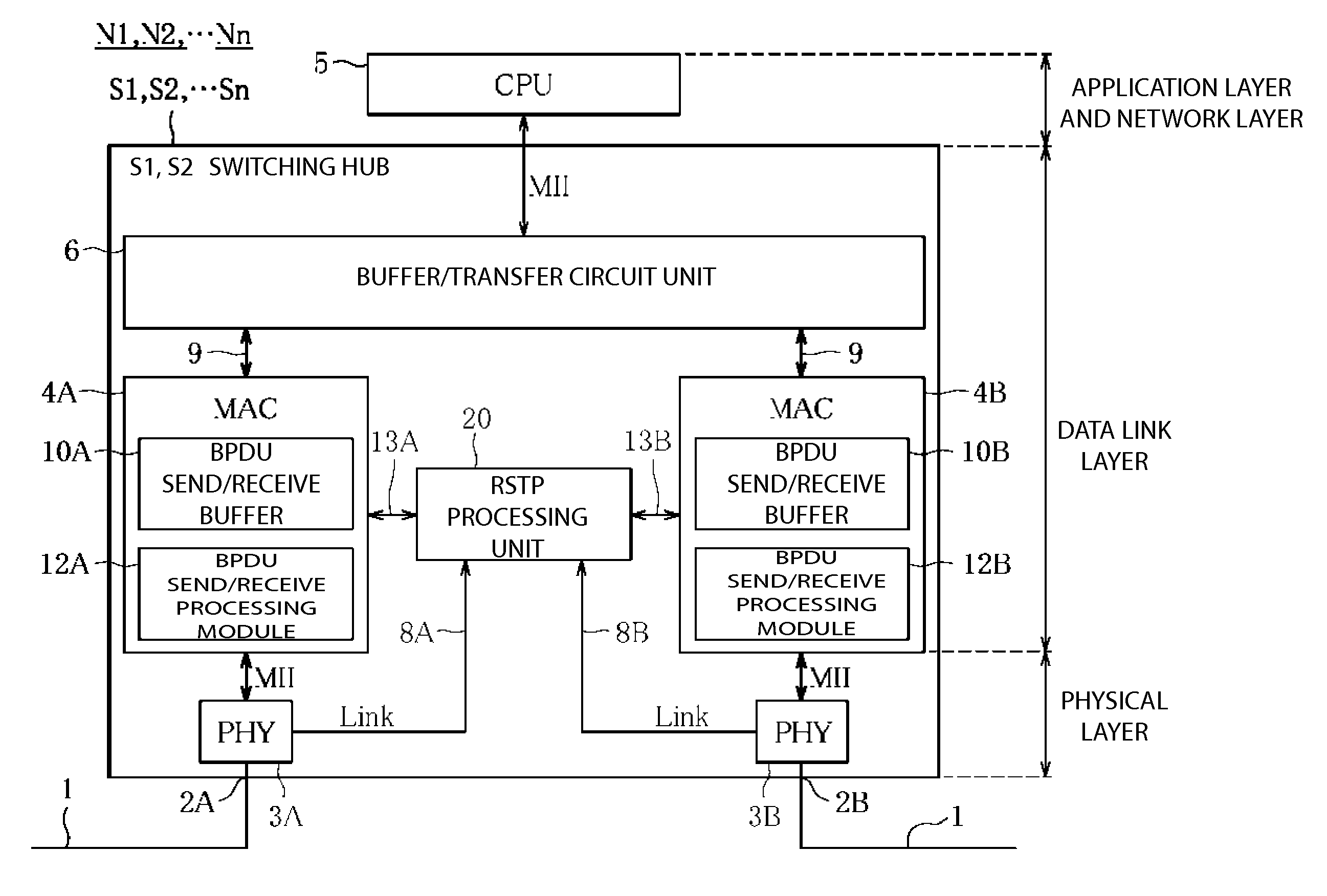
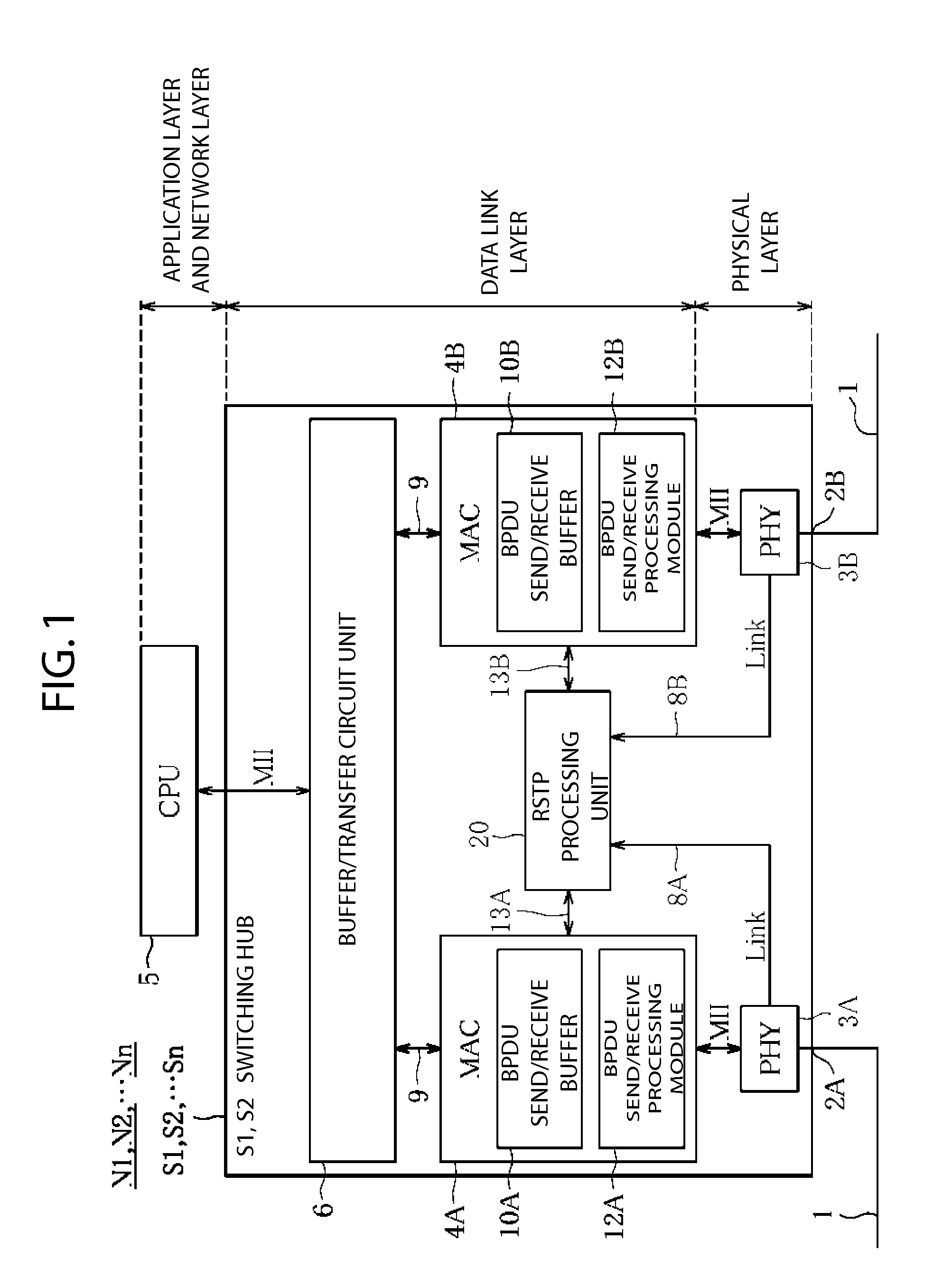
[0025]In the RSTP processing system according to the present invention, the RSTP processing unit, which processes the RSTP, is incorporated as hardware in the
data link layer, the RSTP processing unit and the BPDU send /
receiver buffers of the MAC units are respectively connected by the BPDU data buses, and the RSTP process is executed in the hardware; therefore, BPDUs can be processed at extremely high speeds without the intervention of
software processing.
[0026]Furthermore, if a configuration is adopted wherein the PHY unit has a link
signal line that is used to notify the RSTP processing unit of a failure in the
physical layer level and the RSTP processing unit, when it is notified via the link
signal line of one of the PHY units of a failure in the physical layer level, transmits to the network via the other PHY unit notification BPDU data from the BPDU send / receive buffer that has the MAC unit connected to the other PHY unit, then the RSTP processing unit is notified, via the link
signal, of failures in the physical layer level detected by the PHY unit, and the RSTP processing unit that receives the failure notification via the link signal transmits BPDU data to the network from the BPDU send / receive buffer of the other MAC unit connected to the other PHY unit; therefore, BPDU data can be transferred with extremely small
transmission delay times.
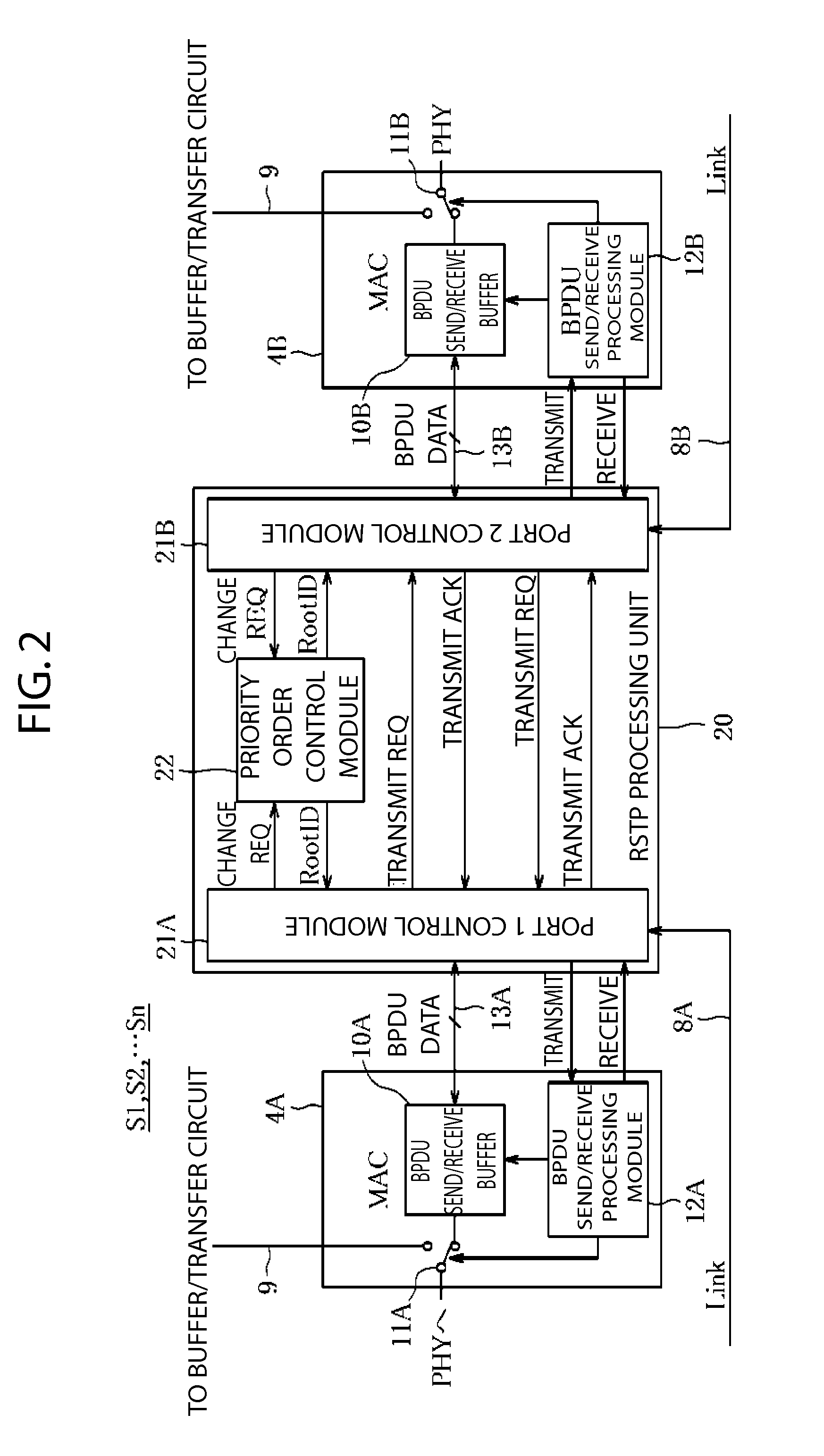
[0027]Furthermore, if a configuration is adopted wherein the RSTP processing unit comprises two port control modules, which control the BPDU send / receive buffers of the two MAC units, and a priority
order control module, which determines the priority level of the local node in the network, and if the BPDU send / receive operations of the two MAC units are performed as a
parallel process, then it is possible to switch at high speed the order of priority of nodes (i.e., to switch the root and the designated) during a recovery; furthermore, the transmission of BPDU data by the two MAC units to neighboring nodes in a
ring network can be processed in parallel via hardware; therefore, it is possible to implement a
network recovery system that can recover from a failure in a short time.
[0028]Furthermore, if a configuration is adopted wherein, in addition to the port control module and the priority
order control module, each of the MAC units comprises: an upper layer data
bus, which transfers send / receive data to and from a CPU, which controls a protocol of an upper layer of the OSI
reference model; a switch unit, which switches the connection of the PHY unit to either the upper layer data bus or the BPDU send / receive buffer; and a BPDU send / receive processing module, that, under the control of the RSTP processing unit, switches the connection destination of the switch unit; and if when either the receive data transferred from one of the PHY units to the corresponding MAC unit or the transmit data transferred from one of the MAC units to the corresponding PHY unit is the BPDU data, the corresponding port control module issues an instruction to the corresponding BPDU send / receive processing module to switch the corresponding switch unit to the corresponding BPDU send / receive buffer side; and when the receive data or the transmit data is not the BPDU data, the corresponding port control module issues an instruction to switch the corresponding switch unit to the corresponding upper layer data bus side, then, when the receive data transferred from one of the PHY units to the corresponding MAC unit is BPDU data, the RSTP processing unit issues an instruction to switch the corresponding switch unit to the corresponding BPDU send / receive buffer side; furthermore, when the receive data is not BPDU data, the RSTP processing unit issues an instruction to the corresponding BPDU send / receive processing module to switch the corresponding switch unit to the corresponding upper layer data bus side; in addition, similarly, if the transmit data is not BPDU data, then the RSTP processing unit issues an instruction to the corresponding BPDU send / receive processing module to switch the corresponding switch unit to the corresponding upper layer data bus side; thereby, enormously practical effects, wherein, for example, it is possible to achieve both the recovery of the network from a failure and the maintenance of communication with the upper layer, are obtained.
[0029]According to the present invention, the RSTP processing system of any of the configurations discussed above can perform at high speed an RSTP process in the
data link layer via hardware and thereby can achieve an RSTP recovery time of less than 10 ms.

