Eureka AIR delivers breakthrough ideas for toughest innovation challenges, trusted by R&D personnel around the world.

Polishing apparatus and program thereof

a technology of polishing apparatus and program, which is applied in the direction of lapping machines, instruments, total factory control, etc., can solve the problems of conventional schedulers, therefore, cannot meet the demand for fully preventing corrosion of copper, and the wait time of waxing cleaning, so as to reduce the decrease of throughput and eliminate the effect of cleaning wait tim

Active Publication Date: 2010-05-27
EBARA CORP
View PDF7 Cites 5 Cited by
  • Summary
  • Abstract
  • Description
  • Claims
  • Application Information

AI Technical Summary

Benefits of technology

[0010]The present invention has been made in view of the above situation. It is therefore an object of the present invention to provide a polishing apparatus and a program stored in the control section of the polishing apparatus, which make it possible to minimize the time period from the termination of polishing of a polishing object to the start of cleaning of the polishing object while maintaining the highest possible throughout.
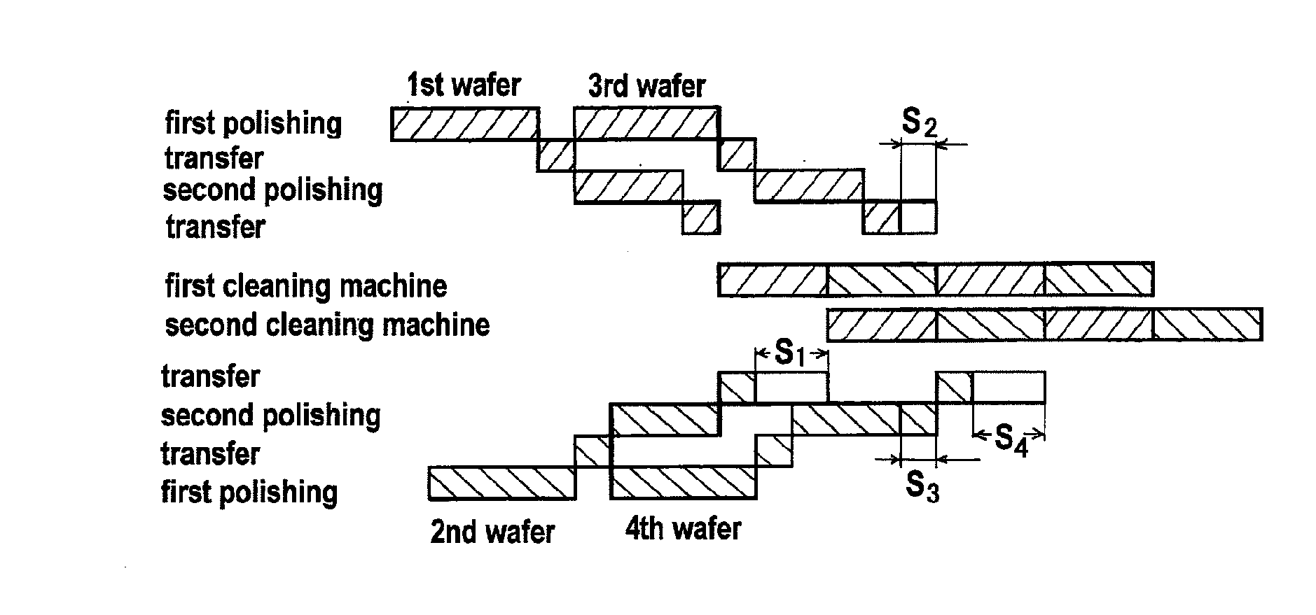
[0012]The present invention provides another polishing apparatus comprising: a loading section for placing therein a cassette in which a plurality of polishing objects are housed; a plurality of polishing lines for polishing a polishing object; a cleaning line having a cleaning machine for cleaning the polishing object after polishing and a transport unit for transporting the polishing object; a transport mechanism for transporting the polishing object between the loading section, the polishing lines and the cleaning line; and a control section for controlling the polishing lines, the cleaning line and the transport mechanism. The control section determines a polishing wait time by subtracting a predicted polishing end time in the case of zero wait time from a predicted cleaning start time in the cleaning line and, when the polishing wait time is positive, delays a polishing start time in each of the polishing lines by the polishing wait time.
[0015]The present invention provides another program stored in a control section of a polishing apparatus, which comprises: a loading section for placing therein a cassette in which a plurality of polishing objects are housed; a plurality of polishing lines for polishing a polishing object; a cleaning line having a cleaning machine for cleaning the polishing object after polishing and a transport unit for transporting the polishing object; a transport mechanism for transporting the polishing object between the loading section, the polishing lines and the cleaning line; and the control section for controlling the polishing lines, the cleaning line and the transport mechanism. The program causes a computer to execute a procedure to determine a polishing wait time by subtracting a predicted polishing end time in the case of zero wait time from a predicted cleaning start time in the cleaning line and, when the polishing wait time is positive, delay a polishing start time in each of the polishing lines by the polishing wait time.
[0017]The present invention makes it possible to eliminate a cleaning wait time between the termination of polishing and the start of cleaning so that a polishing object can be cleansed immediately after polishing while maintaining the highest possible throughput, i.e., minimizing decrease in the throughput. The present invention, when applied in a process for the formation of copper interconnects, for example, can fully prevent corrosion of copper.

Problems solved by technology

Maximizing the throughput, however, can produce a wafer's cleaning wait time between the termination of polishing and the start of cleaning, which will progress corrosion of copper in a copper interconnects-forming process, for example.
Such conventional schedulers, therefore, cannot meet the demand for fully preventing corrosion of copper.

Method used


Image

  • Polishing apparatus and program thereof
  • Polishing apparatus and program thereof
  • Polishing apparatus and program thereof

Examples


Embodiment Construction

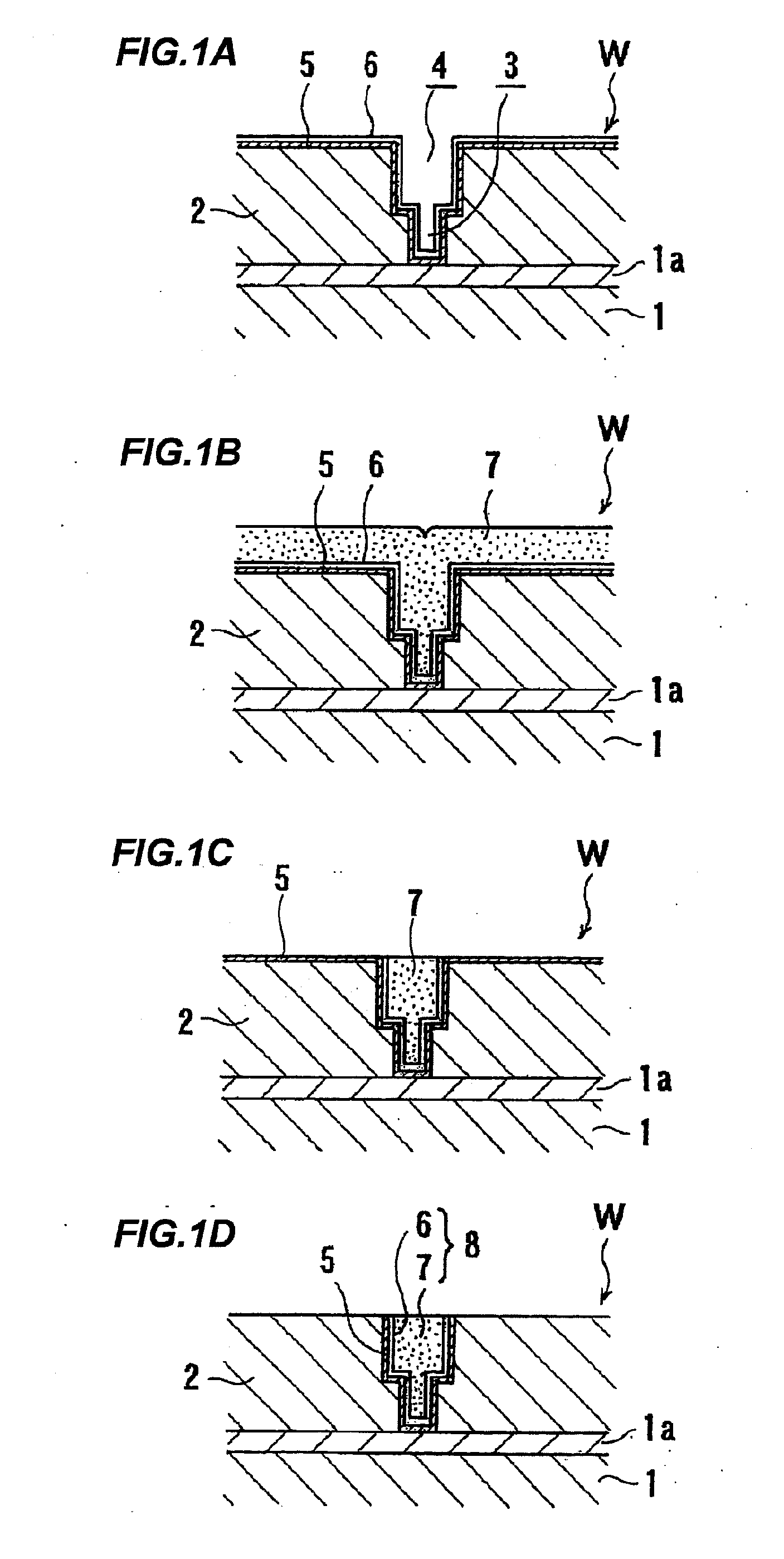
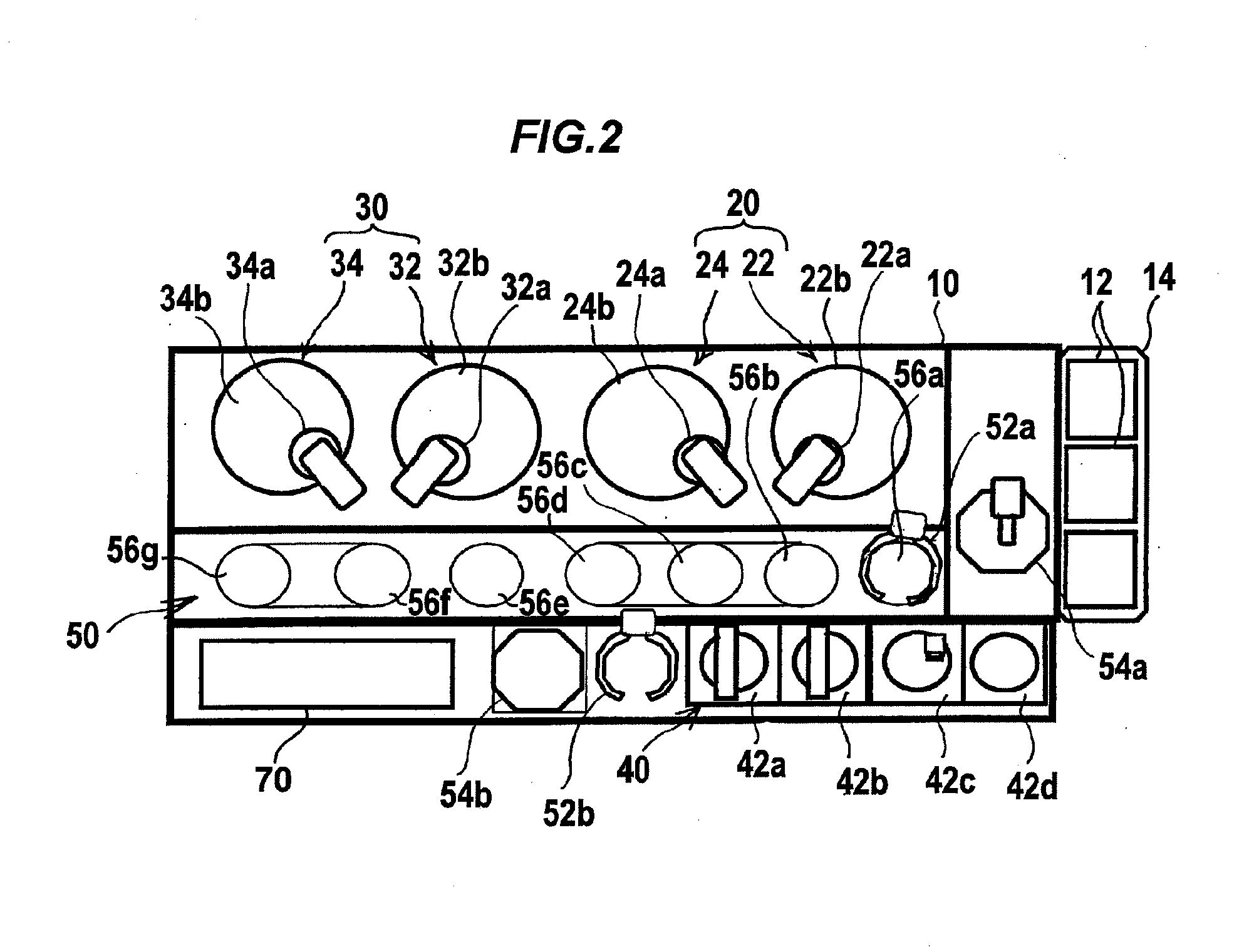
[0030]Preferred embodiments of the present invention will now be described in detail with reference to the drawings. The following description illustrates an exemplified case in which a substrate W as shown in FIG. 1B, having a copper film 7 formed in a surface, is prepared and two-step polishing of the substrate W is carried out in the following manner: First, as shown in FIG. 1C, the copper film 7 and a seed layer 6 on a barrier layer 5 are removed by polishing until the surface of the barrier layer 5 becomes exposed (first polishing); and subsequently, as shown in FIG. 1D, the barrier layer 5 on the insulating film 2 and, if necessary, a surface part of the insulating film 2 are removed by polishing (second polishing). Process control of the below-described polishing apparatus is performed in the control section 70 shown in FIG. 2 in the polishing apparatus, and the process control system is stored as a program in the control section.

[0031]FIG. 2 is an overall plan view schematic...


PUM

PropertyMeasurementUnit
Timeaaaaaaaaaa
Timeaaaaaaaaaa

Abstract

A polishing apparatus includes a loading section (14) for placing therein a cassette (12) in which a plurality of polishing objects are housed; a first polishing line (20) and a second polishing line (30) for polishing a polishing object; a cleaning line (40) having cleaning machines (42a, 42b, 42c, 42d) for cleaning the polishing object after polishing and a transport unit (44) for transporting the polishing object; a transport mechanism (50) for transporting the polishing object between the loading section (14), the polishing lines (20, 30) and the cleaning line (40); and a control section for controlling the polishing lines (20, 30), the cleaning line (40) and the transport mechanism (50). The control section determines a polishing start time in each of the first and second polishing lines (20, 30) based on a predicted polishing time in each of the first and second polishing lines (20, 30), a predicted transport time in the transport mechanism (50), a predicted cleaning time in the cleaning line (40) and a predicted cleaning start time to start cleaning by driving the transport unit (44) of the cleaning line (40).

Description

TECHNICAL FIELD[0001]The present invention relates to a polishing apparatus and a program thereof, and more particularly to a polishing apparatus for polishing a polishing object, such as a semiconductor wafer, into a flat mirror-like surface, and a program stored in a control section of the polishing apparatus.BACKGROUND ART[0002]A process (so-called damascene process), which involves filling a metal (interconnect material) into interconnect trenches and via holes, is currently being used as a process for the formation of interconnects of a semiconductor device. The process technology involves filling a metal such as aluminum, or more recently copper or silver, into interconnect trenches and via holes previously formed in an interlayer dielectric, and then removing an extra metal by chemical mechanical polishing (CMP) into a flat surface.[0003]FIGS. 1A through 1D illustrate, in a sequence of process steps, an exemplary process for forming copper interconnects in a semiconductor dev...

Claims


Application Information

Patent Timeline
IPC IPC(8): B24B1/00B24B37/04H01L21/304
CPCB24B37/042B24B37/345G05B19/41865H01L21/67276G05B2219/45232H01L21/02074H01L21/67219G05B2219/32304Y02P90/02H01L21/304
Inventor NAKAO, HIDETAKAINOUE, MASAFUMITAKEDA, KOICHI
Owner EBARA CORP
Why Eureka
Eureka Blog
Learn More