Work system and information processing method

a work system and information processing technology, applied in the field of work system and information processing method, can solve the problems of limiting a precise measurement range, affecting the achievement of high measurement precision, and occlusion of slit light emitted by the target object or the robot arm depending on the position or orientation of the target object, so as to achieve high measurement precision. the effect of precision

Inactive Publication Date: 2010-05-27
CANON KK
View PDF4 Cites 30 Cited by
  • Summary
  • Abstract
  • Description
  • Claims
  • Application Information

AI Technical Summary

Benefits of technology

[0013]According to the present invention, in a work system which comprises an arm mechanism used to execute a predetermined work while measuring three-dimensional in...

Problems solved by technology

However, when the image sensing device and slit light projector are arranged at the global position, occlusion of slit light emitted by the slit light projector by the target object itself or the robot arm cannot be avoided depending on the position or orientation of the target object.
Also, the focal depth of the emitted slit light often limit a precise measurement range.
These problems disturb ac...

Method used


Image

  • Work system and information processing method
  • Work system and information processing method
  • Work system and information processing method

Examples


first embodiment

[0034]

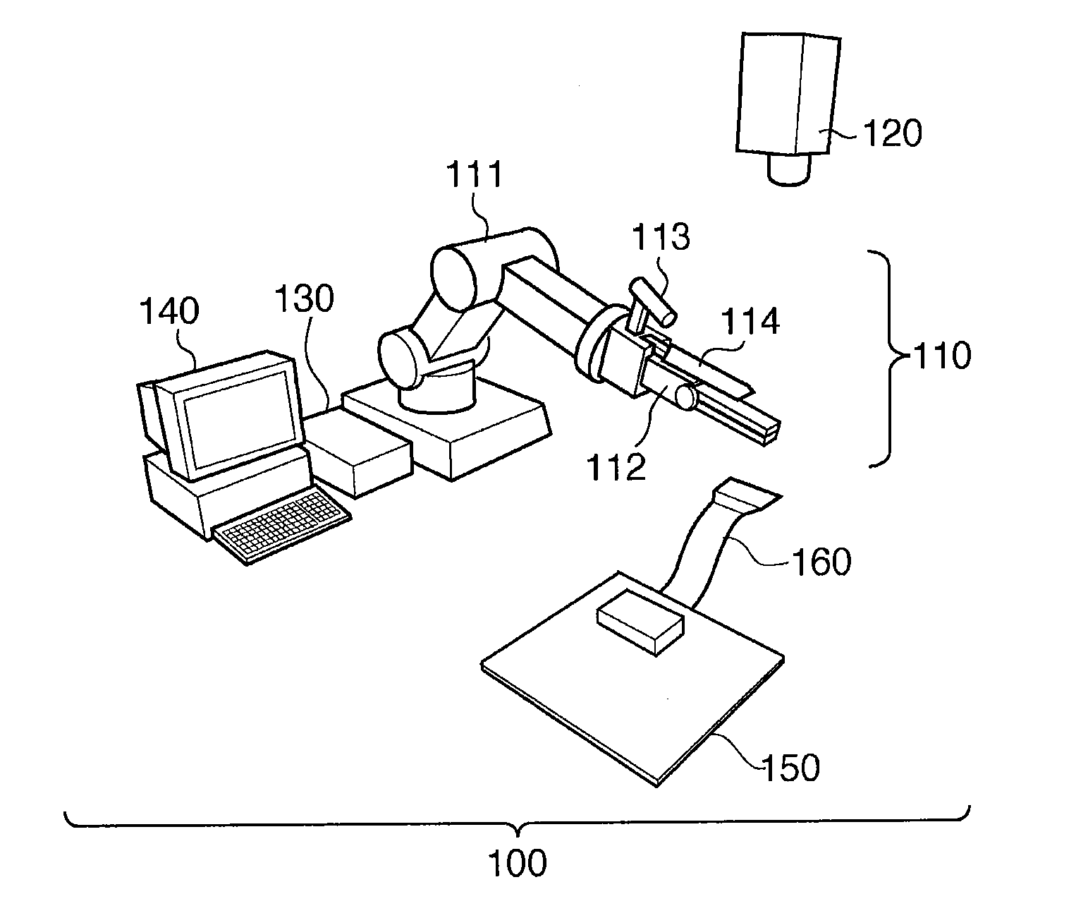
[0035]FIG. 1 is a view showing the outer appearance arrangement of a work system 100 according to the first embodiment of the present invention. Referring to FIG. 1, reference numeral 110 denotes a work unit which includes an arm mechanism used to execute a predetermined work for an object to be processed (target object). Reference numeral 111 denotes a robot arm. A robot hand 112 as a member (end effecter) which contacts the target object and executes the predetermined work is attached to the distal end portion of the robot arm 111. Note that the robot arm 111 and robot hand 112 will be collectively referred to as an arm mechanism hereinafter.

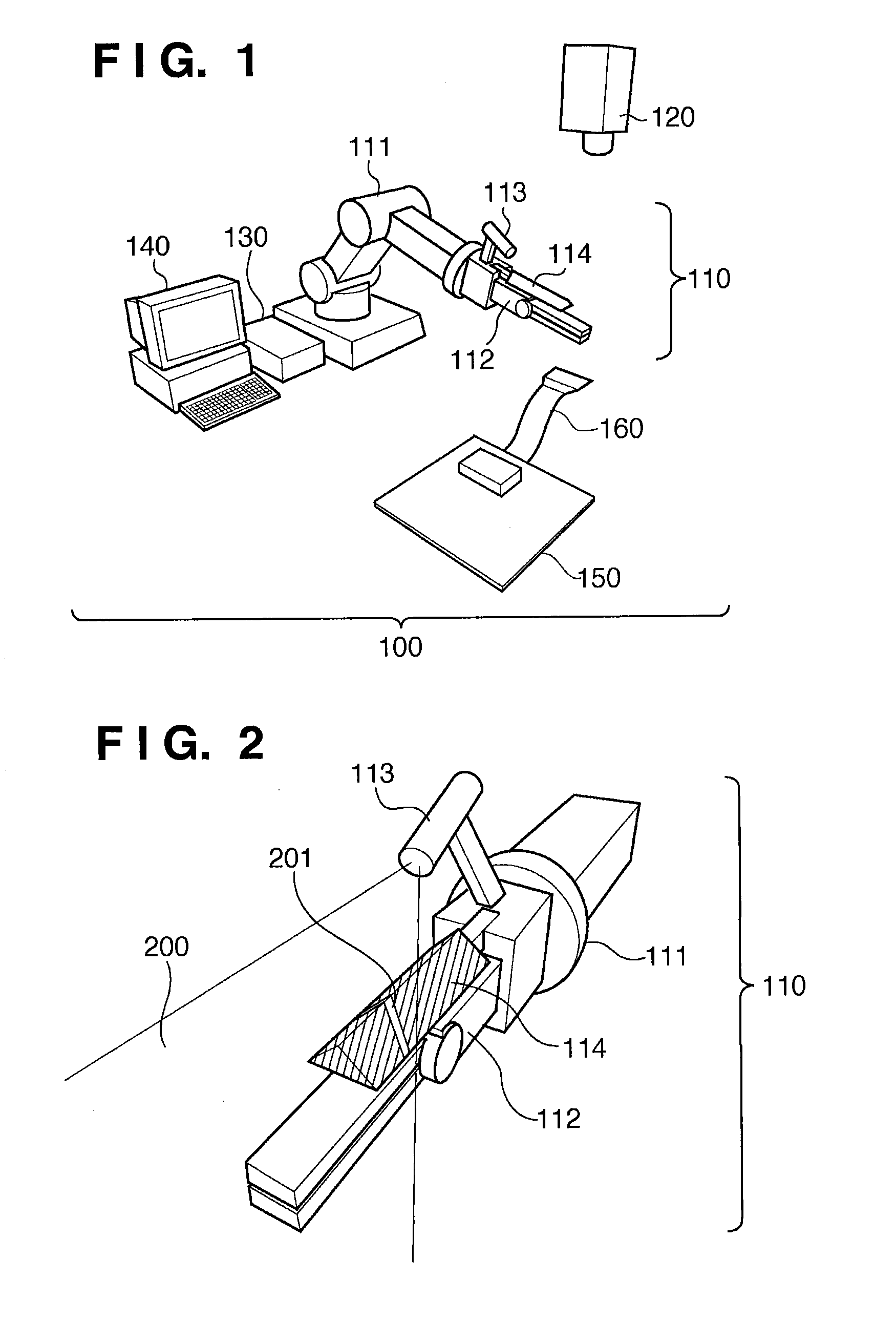
[0036]Reference numeral 113 denotes a slit laser projector (slit light projector) which serves as a light projection unit. The slit laser projector 113 is attached to the distal end portion of the robot arm 111, and emits laser slit light as pattern light.

[0037]Reference numeral 114 denotes a hand position detection member which serves a...

second embodiment

[0129]The work processing in the first embodiment is premised on that 3D information enough to execute a work in step S807 (work process) is calculated in step S804.

[0130]However, 3D information required to uniquely estimate, for example, the position and orientation of the target object 160 as the calculation result in step S804 may not be obtained in some cases. Thus, this embodiment will explain work processing premised on that 3D information that suffices to execute a work in step S807 (work process) cannot often be obtained.

[0131]Note that the outer appearance arrangement, functional arrangement, and calibration processing of the work system according to this embodiment are basically the same as those of the work system according to the first embodiment, and a description thereof will not be repeated.

[0132]FIG. 9 is a flowchart showing the sequence of work processing in the work system according to this embodiment.

[0133]In step S901 (measurement movement process) to step S904 (...

third embodiment

[0138]In the first embodiment, the irradiation angle of slit light to be emitted is fixed, and the shape of the hand position detection member is defined to uniquely determine the position and orientation of the robot arm 111 based on the sensed light-section line 201.

[0139]However, the present invention is not limited to this. For example, the irradiation angle of slit light to be emitted by the slit laser projector 113 may be variable so as to uniquely determine the position and orientation of the robot arm 111. Details of this embodiment will be described below.

[0140]

[0141]FIG. 10 is a view showing the outer appearance arrangement of a work unit of a work system according to this embodiment. Referring to FIG. 10, reference numeral 1003 denotes a movable galvano mirror or polygon mirror, which serves as a light scanning unit. As shown in FIG. 10, the light scanning unit 1003 is arranged on the front portion of the slit laser projector 113 to change the irradiation angle of a light...


PUM


Abstract

In a work system which measures 3D information of a target object by a light-section method, high measurement precision is realized. The invention includes a robot arm, a hand position detection member which is arranged at the distal end portion of the robot arm, a slit laser projector which irradiates slit light, a camera which is fixed at a position independent of the robot arm, and senses an image of the target object, and a computer which calculates a light-section plane of the slit light based on a light-section line formed on the hand position detection member which is included in image data of the target object obtained by image sensing by the camera, and calculates the position and orientation of the target object based on the calculated light-section plane and the light-section line formed on the target object.

Description

BACKGROUND OF THE INVENTION[0001]1. Field of the Invention[0002]The present invention relates to a work system which includes an arm mechanism used to execute a predetermined work for a target object, and an information processing method in the work system.[0003]2. Description of the Related Art[0004]In a work system which includes an arm mechanism used to execute a predetermined work for a target object whose position and orientation change, the position and orientation (three-dimensional (3D) information) of the target object are required to be measured upon execution of the work, and a light-section method is known as the measuring method.[0005]The light-section method is a method that acquires 3D information of the target object by executing a triangulation by combining a camera and slit light projector, and various proposals about this method have been conventionally made in association with application to the work system.[0006]For example, Japanese Patent Laid-Open No. 2005-27...

Claims


Application Information

Patent Timeline
IPC IPC(8): G06F15/00G01B11/14
CPCG01B11/2518G06T7/70G01B11/2504G01B11/24B25J9/1697G01B11/25
Inventor AOBA, MASATO
Owner CANON KK
Why Eureka
Try Eureka