Thermal management of urea dosing components in an engine exhaust after-treatment system

a technology of exhaust aftertreatment and urea, which is applied in the direction of exhaust treatment electric control, machines/engines, mechanical equipment, etc., can solve the problems of reducing the effectiveness adversely affecting the life and performance of the aftertreatment system, etc., and achieves the reduction of the overall length of the associated fluid conduit, the effect of simplifying the dosing system and reducing the complexity of the connection hardwar

Active Publication Date: 2010-06-03
INT ENGINE INTPROP CO LLC
View PDF4 Cites 36 Cited by
  • Summary
  • Abstract
  • Description
  • Claims
  • Application Information

AI Technical Summary

Benefits of technology

[0007]While the invention accomplishes thermal management of tank, pump, and injector in a way that provides the needed temperature regulation of dosing solution, it can also simplify the dosing system by reducing overall lengths of associated fluid conduits and complexity of connection hardware. Because the flow of engine coolant through the injector, in accordance with certain principles of the invention, can return to the engine cooling system only after having passed through either the tank, the pump or both, the invention is effective to pass heat that has been transferred from exhaust gases to the injector along to the tank, the pump, or both. In cold ambient temperatures, this can accelerate the thawing of frozen solution in the tank, pump, and / or associated conduits, aiding in achieving compliance with some specified time limit within which the reductant must become effective on the exhaust gas via SCR catalytic action.

Problems solved by technology

It is important for injected urea solution to completely evaporate because incomplete evaporation can lead to undesired consequences such as the formation of solid deposits in the exhaust system that can adversely affect the life and performance of the after-treatment system.
In cold ambient temperatures near and below about 12° F., the liquid in the tank, pump, and associated conduits can freeze while in hot ambient temperatures, the solution can become unstable, significantly reducing its effectiveness when injected into the after-treatment system.

Method used


Image

  • Thermal management of urea dosing components in an engine exhaust after-treatment system
  • Thermal management of urea dosing components in an engine exhaust after-treatment system

Examples


Embodiment Construction

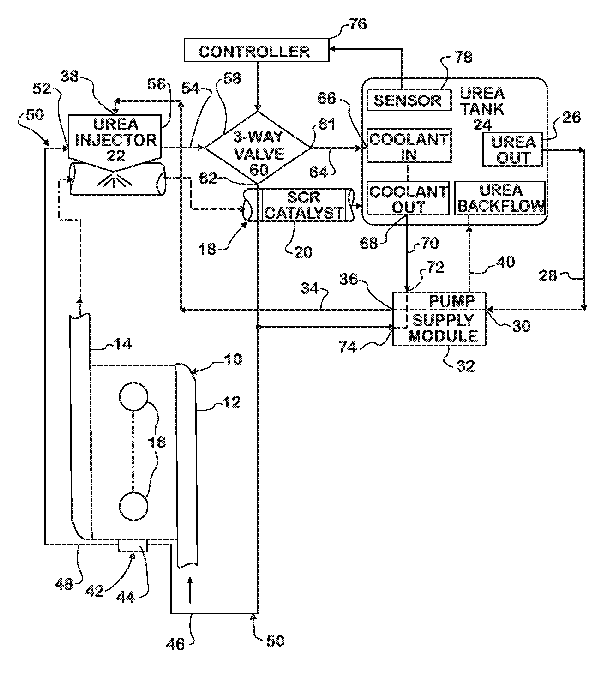
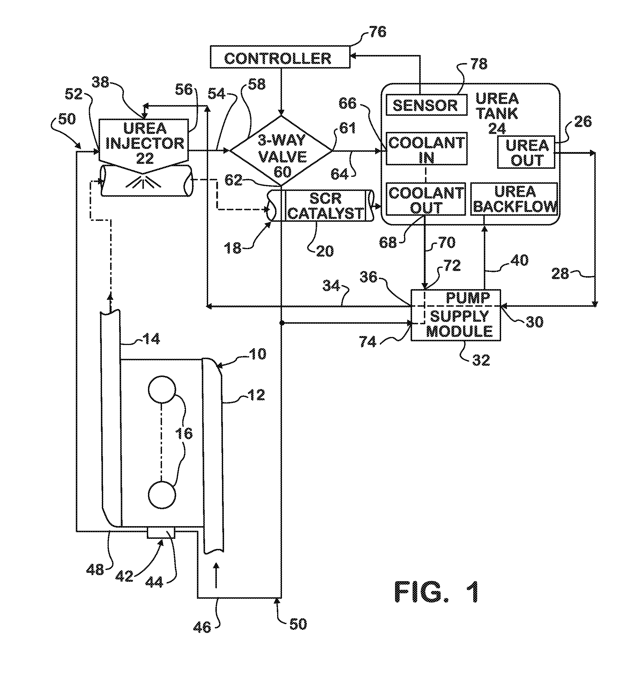
[0023]FIG. 1 shows a diesel engine 10 comprising an intake system 12 through which charge air enters and an exhaust system 14 through which exhaust gas resulting combustion exits, not all details of those two systems that are typically present being shown. Engine 10 comprises a number of cylinders 16 forming combustion chambers into which fuel is injected by fuel injectors to combust with the charge air that has entered through intake system 12. Energy released by combustion powers the engine via pistons connected to a crankshaft. When used to propel a motor vehicle, such as a truck, engine 10 is coupled through a drivetrain to driven wheels that propel the vehicle. Intake valves control the admission of charge air into cylinders 16, and exhaust valves control the outflow of exhaust gas through exhaust system 14 and ultimately to atmosphere. Before entering the atmosphere however, the exhaust gas is treated by one or more after-treatment devices in an after-treatment system 18.

[0024...


PUM


Abstract

Dosing components (22, 24, 32) in an engine exhaust after-treatment system (18) that includes an SCR catalyst (20) are thermally managed by flowing engine coolant through a coolant passage in a urea injector (22) that injects aqueous urea into the after-treatment system, controlling a three-way valve (60) to selectively direct coolant flow leaving the urea injector to a first branch that is in heat exchange relationship with a tank (24) that holds a supply of aqueous urea and a supply pump module (32) that pumps aqueous urea from the tank to the urea injector, and a second branch that is not in heat exchange relationship with either the tank or the supply pump, and returning coolant from the branches to the engine cooling system.

Description

FIELD OF THE INVENTION[0001]This invention relates to internal combustion engines, especially motor vehicle engines that utilize dosing, such as urea dosing, for after-treatment of engine exhaust.BACKGROUND OF THE INVENTION[0002]The performance of a diesel engine after-treatment system in converting NOx to other products by selective catalytic reduction (SCR) relies on the presence of ammonia in the exhaust stream. Dosing engine exhaust by injection of aqueous urea, an ammonia-based reductant, into the exhaust stream at a location upstream of an SCR catalyst is one way to introduce ammonia into the exhaust system.[0003]It is important for injected urea solution to completely evaporate because incomplete evaporation can lead to undesired consequences such as the formation of solid deposits in the exhaust system that can adversely affect the life and performance of the after-treatment system.[0004]A known design practice places a urea injector at a location in the engine exhaust syste...

Claims


Application Information

Patent Timeline
Patent Type & Authority Applications(United States)
IPC IPC(8): F01N9/00F01N3/10F01N5/02
CPCF01N3/043F01N3/2066F01N3/208F01N5/02F01N2240/02F01N2260/024Y02T10/24F01N2610/02F01N2610/10F01N2610/14F01N2610/146Y02T10/16F01N2560/06Y02T10/12
Inventor SCHMALE, MARKGRIFFIN, GREGORY A.
Owner INT ENGINE INTPROP CO LLC
Why Eureka
Try Eureka