Ignition apparatus with cylindrical core and laminated return path

a technology of a return path and a cylindrical core, which is applied in the direction of cores/yokes, mechanical equipment, machines/engines, etc., can solve the problems of a significant portion of the total bill of materials (bom), the cost of copper wire in the ignition coil has become a significant portion of the total bill of materials, etc., and achieves a high permeance magnetic path, reduce the amount of copper wire, and reduce the amount of mlt

Active Publication Date: 2010-06-03
DELPHI TECH IP LTD
View PDF10 Cites 13 Cited by
  • Summary
  • Abstract
  • Description
  • Claims
  • Application Information

AI Technical Summary

Benefits of technology

[0005]One advantage of the present invention is that it reduces the amount of copper wire used as compared to conventional ignition coils for comparable performance. The present invention achieves this advantage by providing a winding structure that allows for the use of a circular-shaped magnetic core (i.e., where the primary winding can be wound directly around the core to reduce the MLT) in combination with a return structure that provides a high permeance magnetic path (i.e., which generally permits a reduction in the number of turns). Overall, the amount of copper wire used, and hence copper material, is reduced.
[0006]In one embodiment, an ignition apparatus is provided that includes a magnetically-permeable core, a primary winding, a secondary winding and a magnetically-permeable structure defining a high permeance magnetic return path. The core is generally cylindrical, extends along an axis, and has a pair of end surfaces on axially-opposite ends thereof. The core thus has a circular shape in radial cross-section. Accordingly, the mean length per turn (MLT) is reduced relative to other arrangements, as described in the Background. The structure, which comprises a stack of silicon steel laminations, may be roughly in a C-shape, and have a base and a pair of legs that extend from the base. The core is positioned so that the end surfaces face the pair of legs. Preferably, at least one of the end surfaces is spaced apart from its nearest leg to form a relatively small air gap, thus establishing a magnetic circuit with high magnetic permeability. Accordingly, the number of turns of the primary winding can be reduced. The present invention thus incorporates, in combination, a MLT-reducing circular core structure with a turn-reducing high magnetic permeability magnetic return path.
[0007]In an alternate embodiment, the C-shaped structure is replaced with a magnetically-permeable shield. The shield includes a main, U-shaped section and a pair of end caps configured to close opposing ends of the U-shaped section to define an closed interior having an opening to access the interior. The interior is configured to house the central components described above. In a preferred embodiment, the interior is filled with epoxy potting material to encapsulate the interior components. The shield includes tabs configured to retain the encapsulated components in the interior of the shield.
[0008]Other aspects, features and advantages are also presented.

Problems solved by technology

While there has always been an incentive to reduce the amount of copper wire in an ignition coil (and hence the cost attributable to copper), in the past few years, the price of copper has increased over 400%, with the result that the cost of the copper wire in an ignition coil has become a significant portion of the total bill of materials (BOM).

Method used


Image

  • Ignition apparatus with cylindrical core and laminated return path
  • Ignition apparatus with cylindrical core and laminated return path
  • Ignition apparatus with cylindrical core and laminated return path

Examples


Embodiment Construction

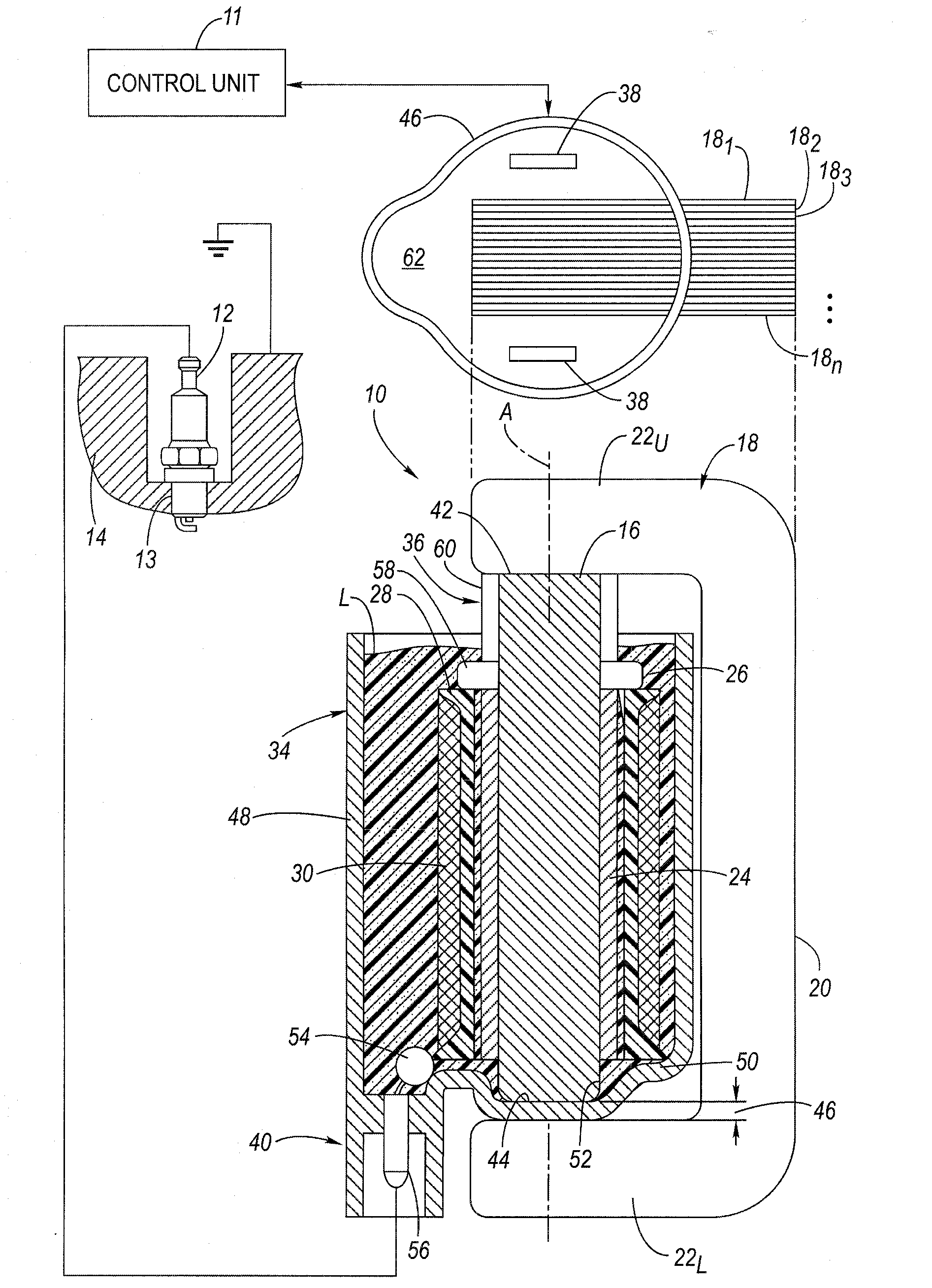
[0014]Referring now to the drawings wherein like reference numerals are used to identify identical components in the various views, FIG. 1 (first embodiment) is a simplified side view, with portions shown in cross-section, of an ignition apparatus 10. The ignition apparatus 10 may be controlled by a control unit 11 or the like. The ignition apparatus 10 is configured for connection to a spark plug 12 that is in threaded engagement with a spark plug opening 13 into a combustion cylinder in an internal combustion engine 14. The ignition apparatus 10 is configured to output a high-voltage (HV) output to the spark plug 12, as shown. Generally, overall spark timing (dwell control) and the like is provided by the control unit 11. One ignition apparatus 10 may be provided per spark plug 12.

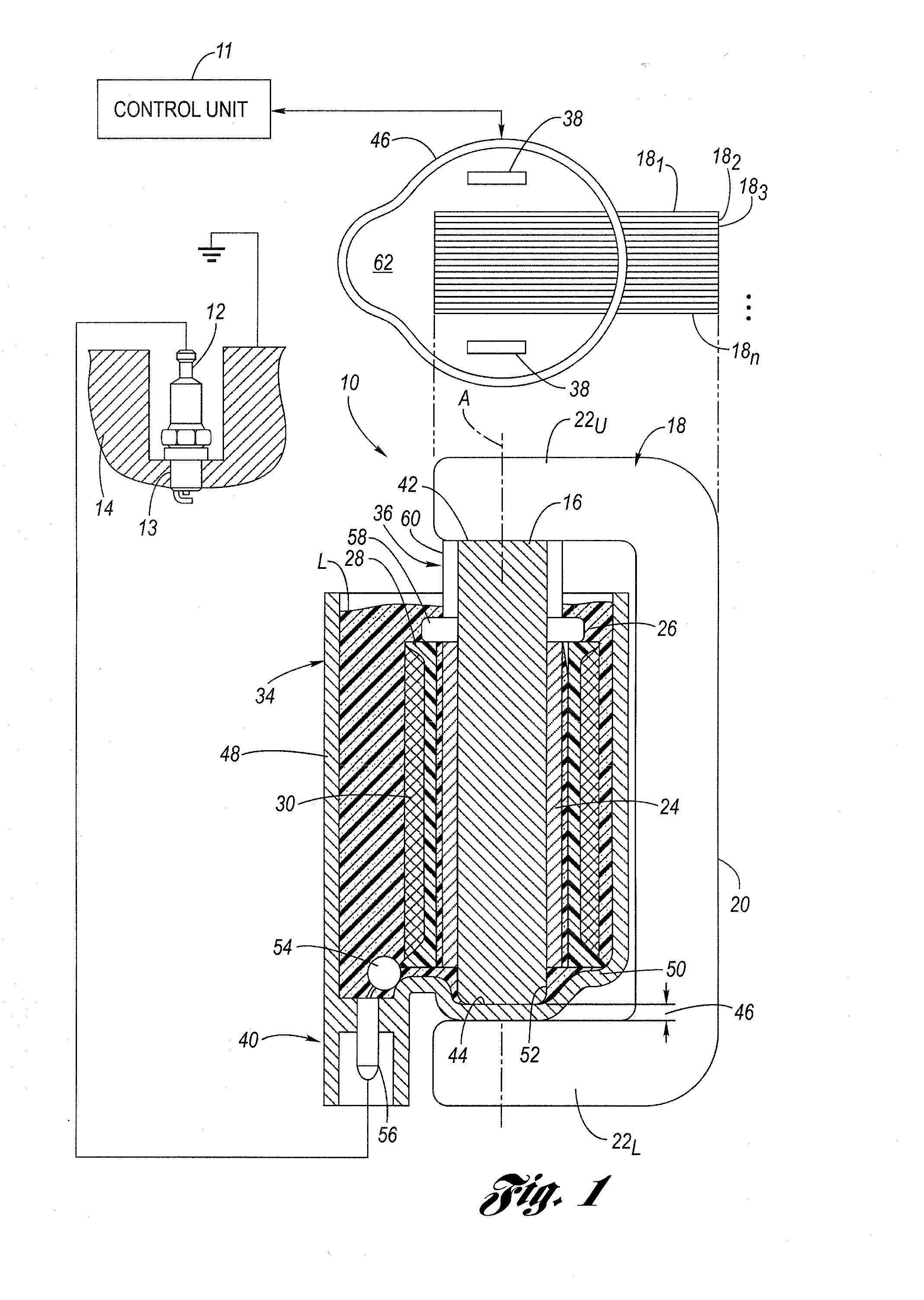
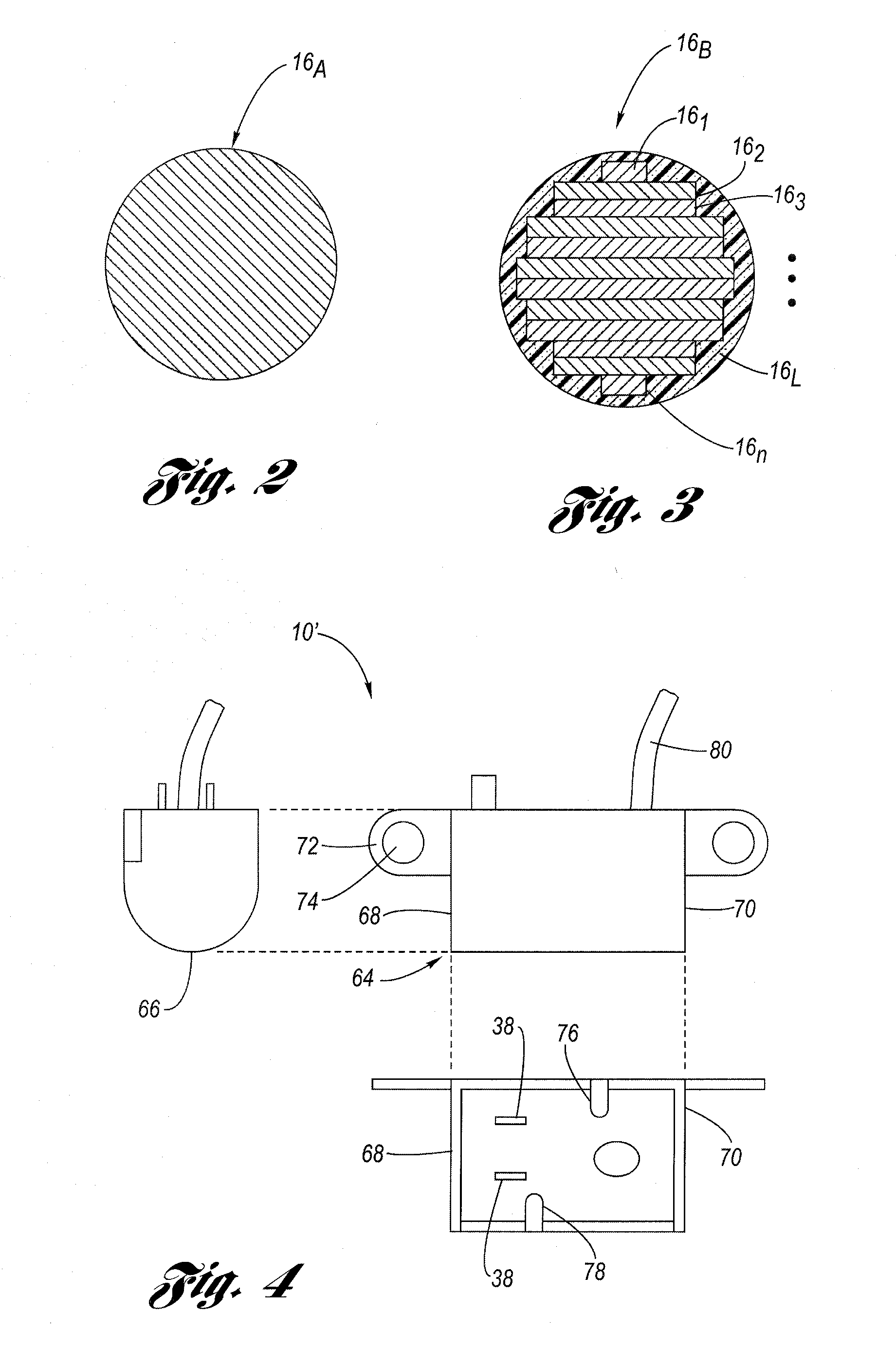
[0015]The ignition apparatus 10 may include a magnetically-permeable core 16, optional first and / or second magnets (not shown) at one or both ends of the core 16, a magnetically-permeable structure 18 co...


PUM


Abstract

An ignition apparatus includes a cylindrical core made from magnetically-permeable material and a C-shaped magnetic return path structure that is made from a stack of silicon steel laminations. A tightly controlled air gap is provided between one leg of the C-shaped structure and an end face of the core, forming a magnetic circuit having a high magnetic permeability, which overall reduces the number of primary winding turns needed, thereby reducing the amount of copper wire. In addition, the circular cross-section of the core reduces the mean length per turn (MLT) of the primary winding because the primary winding can be wound directly on the core, which in turn also reduces the MLT of the secondary winding. The reduced MLT also reduces the amount of copper wire. The structure may be replaced using a magnetically-permeable, U-shaped shield.

Description

TECHNICAL FIELD[0001]The present invention relates generally to an ignition apparatus or coil, and, more particularly, to an ignition apparatus that uses less copper wire than conventional arrangements.BACKGROUND OF THE INVENTION[0002]There has been much investigation in the development of an ignition apparatus for producing a spark for ignition of an internal combustion engine. As a result, the art has developed a variety of different configurations suited for many different applications. In general, it is known to provide an ignition apparatus that utilizes a high-voltage transformer that includes a magnetically-permeable core and primary and secondary windings. It is typical to use copper wire for the primary and secondary windings.[0003]While there has always been an incentive to reduce the amount of copper wire in an ignition coil (and hence the cost attributable to copper), in the past few years, the price of copper has increased over 400%, with the result that the cost of the...

Claims


Application Information

Patent Timeline
Patent Type & Authority Applications(United States)
IPC IPC(8): F02P3/02
CPCF02P3/0407H01F3/14H01F38/12H01F27/263H01F27/324H01F27/022H01F1/24
Inventor SKINNER, ALBERT A.WOLF, EDGARDHAMER, COLIN J.SCAFF, ANDRE V.
Owner DELPHI TECH IP LTD
Why Eureka
Try Eureka