Control device for electric rotating machine and method of controlling the machine

a technology of control device and electric rotating machine, which is applied in the direction of programme control, dynamo-electric converter control, instruments, etc., can solve the problems of discontinuous change of controlled voltage and difficulty in maintaining a and achieve the effect of high controllability of the machin

Active Publication Date: 2010-06-03
DENSO CORP
View PDF15 Cites 52 Cited by
  • Summary
  • Abstract
  • Description
  • Claims
  • Application Information

AI Technical Summary

Benefits of technology

[0021]With these steps, even when the machine is operated in an operating state corresponding to a high modulation factor, the controlled variable of the machine can be controlled by controlling a power inverter circuit applying a controlled voltage to the machine, and a high controllability for the machine can be maintained.

Problems solved by technology

However, when the operation of the machine is transferred to the operating state corresponding to a high modulation factor, the controlled voltage is discontinuously changed.
Therefore, it is difficult to maintain a high controllability for the machine.

Method used


Image

  • Control device for electric rotating machine and method of controlling the machine
  • Control device for electric rotating machine and method of controlling the machine
  • Control device for electric rotating machine and method of controlling the machine

Examples


first embodiment

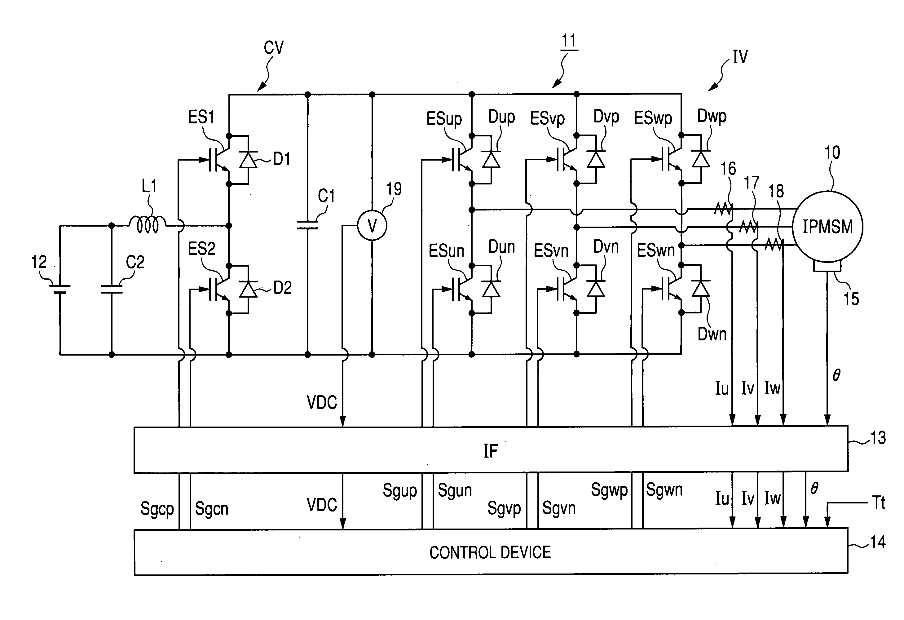
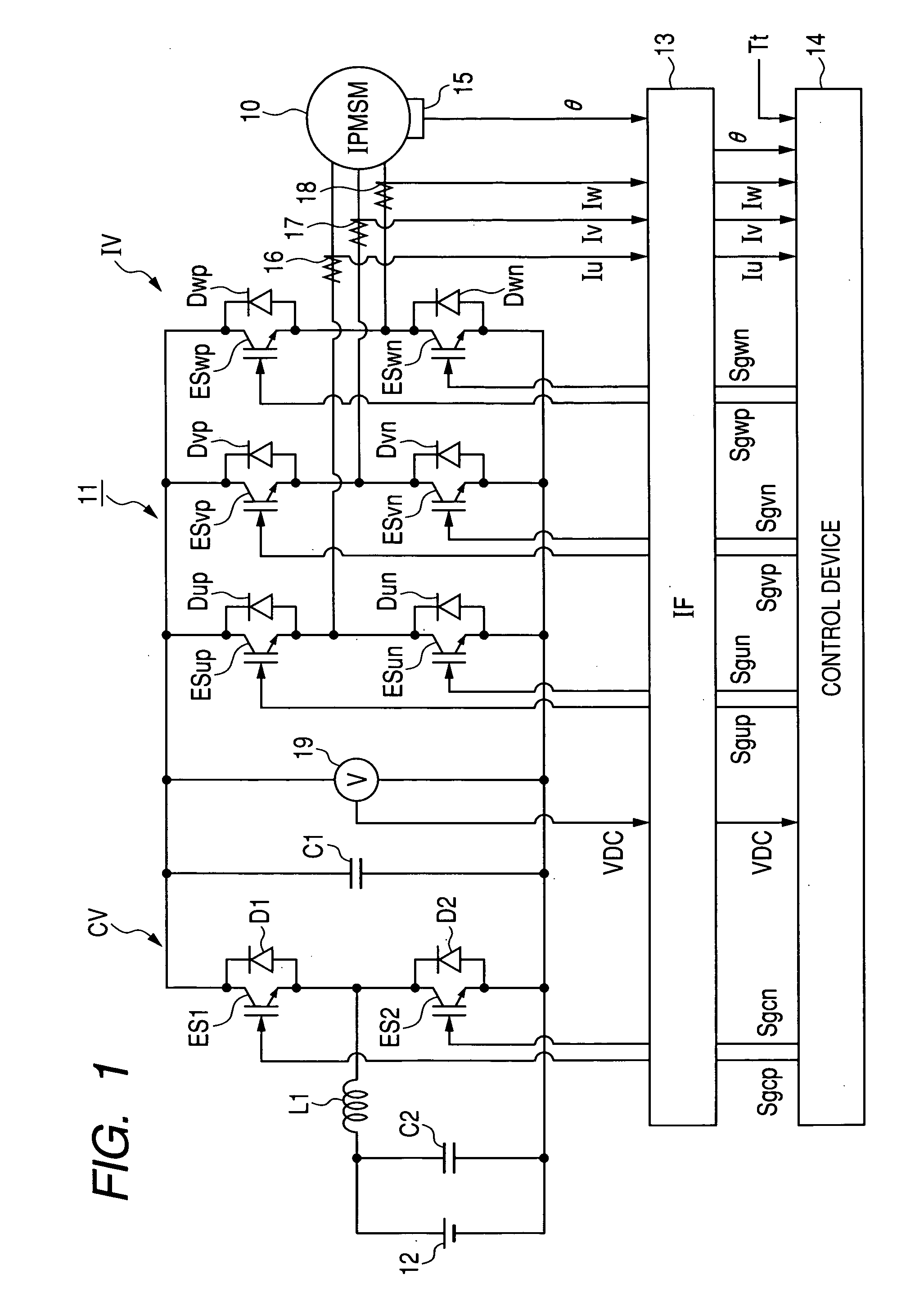
[0058]FIG. 1 is a view showing the structure of a control system for a motor generator according to the first embodiment.

[0059]As shown in FIG. 1, electric power of a high-voltage battery 12 is adjusted in a control system 11 and is supplied to a motor generator 10. This power generating system including the generator 10, the system 11 and the battery 12 is, for example, mounted on a hybrid vehicle. The generator 10 represents an electric rotating machine whose feature is the presence of magnetic saliency. More specifically, the generator 10 is a three-phase interior permanent magnet synchronous motor (IPMSM). This motor has a rotor, permanent magnets having salient poles and being disposed around a shaft of the rotor so as to be protruded from the shaft, a stator surrounding the rotor, and three windings (i.e., a u-phase winding, a v-phase winding and a w-phase winding) wound on the stator.

[0060]The control system 11 has a boost converter CV for boosting the voltage (e.g., 288V) of...

second embodiment

[0185]In the first embodiment, the quantitative value Q1 of the higher harmonic waves is estimated according to the relation (c3). Therefore, the contribution of each higher-order harmonic wave on the quantitative value Q1 is substantially the same as the contribution of any of the other higher-order harmonic waves on the quantitative value Q1.

[0186]However, as the order of the higher harmonic wave becomes low, torque ripple caused in the torque of the generator 10 by the higher harmonic wave of the controlled voltage Vc is increased. To reduce the torque ripple caused by the higher harmonic waves, it is preferable that, as the order of the higher harmonic wave becomes low, the contribution of the higher harmonic wave on the quantitative value Q1 is decreased.

[0187]In the second embodiment, to decrease the contribution of the higher harmonic wave on the quantitative value Q1 as the order of the higher harmonic wave becomes low, the amplitude of each n-th higher order (n=2, 3, 4, . ....

third embodiment

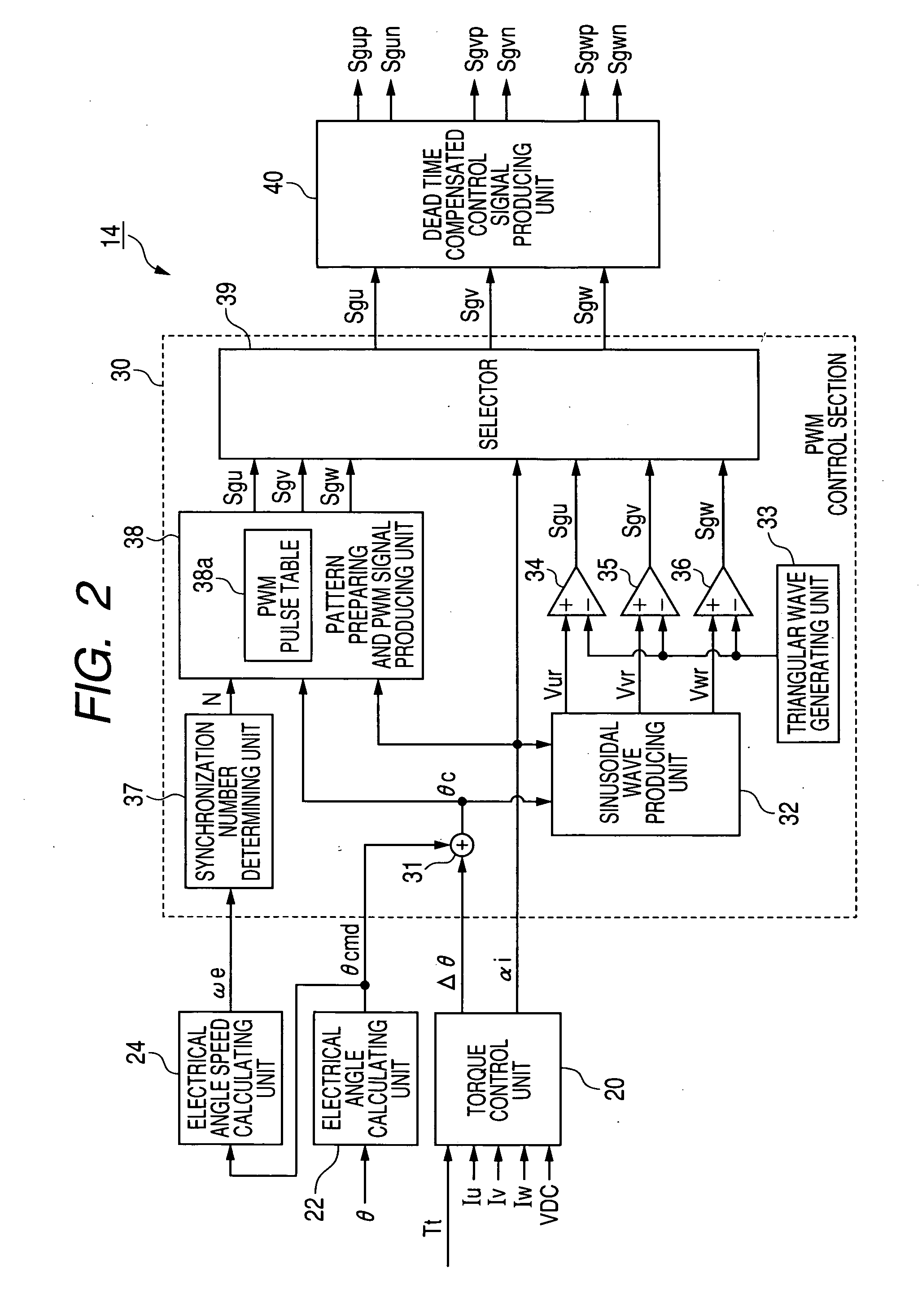
[0196]In the first embodiment, to control the switching elements of the inverter IV and the generator 10 in the pulse pattern control, the production of the PWM signals Sgu, Sgv and Sgw in the control device 14 is performed according to the rotational angle θ detected by the sensor 15. More specifically, the sensor IS renews the angle θ every detecting timing, and the changing timing of the PWM signals is synchronized with the detecting timing of the sensor 15. This synchronization is called angle synchronization based on the angle θ.

[0197]However, when the electrical angular speed we of the generator 10 is low, the phase of the controlled voltage Vc outputted from the inverter IV is controlled at a low controllability. The reason is that the minimum value Δθ(=2πP / C; P denotes the number of pole pairs in the generator 10) detectable by the sensor 15 is fixed due to the resolution C of the sensor 15, regardless of the angular speed as ωe. For example, when the electrical angle cycle ...


PUM


Abstract

A control device has a unit for preparing a pattern having first and second periods by comparing a triangular wave and a sine wave having an amplitude ratio set at each value of a modulation factor, and selecting one pattern corresponding to an instructed modulation factor, and a unit for applying a controlled voltage, set at low and high levels in response to first and second periods of the selected pattern, to a generator. The triangular wave has a cycle duration obtained by dividing the cycle duration of the generator by product of 3 and odd number, a crest having a level higher than the sine wave at a timing of each first period, and a trough having a level lower than the sine wave at a timing of each second period.

Description

CROSS-REFERENCE TO RELATED APPLICATION[0001]This application is based, upon and claims the benefit of priority of the prior Japanese Patent Application 2008-303626 filed on Nov. 28, 2008 and the prior Japanese Patent Application 2009-251333 filed on Oct. 30, 2009, so that the contents of which are incorporated herein by reference.BACKGROUND OF THE INVENTION[0002]1. Field of the Invention[0003]The present invention relates to a control device which controls a controlled variable of a multiphase electric rotating machine by controlling switching elements of a power inverter circuit through which terminals of the electric rotating machine are electrically connected with positive and negative electrodes of a direct current power source, and also relates to a method of controlling the electric rotating machine by using the control device.[0004]2. Description of Related Art[0005]A control device for a three-phase motor has been used. For example, to control three phase currents, actually ...

Claims


Application Information

Patent Timeline
Patent Type & Authority Applications(United States)
IPC IPC(8): B23Q35/00H02P27/06H02P27/08
CPCH02M7/53875H02P23/0027H02P2101/45H02P2201/09H02P2207/05H02P27/08
Inventor YAMADA, TAKAHIROMORIOKA, TATSURUMIYACHI, JUNJI
Owner DENSO CORP
Why Eureka
Try Eureka