
Fan and motor control device

a control device and motor technology, applied in the direction of motor/generator/converter stopper, dynamo-electric converter control, instruments, etc., can solve the problems of /sub>cannot, the voltage level of direct current voltage, etc., to reduce harmonics and reactive power, reduce noise generated by shifting, and reduce consumption

Active Publication Date: 2010-06-03
DELTA ELECTRONICS INC
View PDF4 Cites 6 Cited by
  • Summary
  • Abstract
  • Description
  • Claims
  • Application Information

AI Technical Summary

Benefits of technology

[0007]One objective of the present invention is to provide a motor control device with a power factor correction circuit capable of reducing harmonics and reactive power generated by a motor and controlling the rotational speed of the motor through a regulable voltage level provided by the power factor correction circuit, so as to decrease the noise generated by shifting in the electronic elements of a brushless DC motor and decrease the consumption caused by shifting in the electronic elements.
[0008]Another objective of the present invention is to provide a motor control device with a power factor correction circuit which can be closed for reducing the consumption of a motor while the motor is idling or in light load.
[0011]The above-mentioned motor control device further includes a voltage regulating unit and a controlling unit. The voltage regulating unit is electrically connected with the step-up unit for regulating the second voltage. The controlling unit is electrically connected with the voltage regulating unit and the processing unit, and when the controlling unit receives a first controlling signal outputted by the processing unit, the controlling unit regulates the second voltage through the voltage regulating unit. Or, the processing unit can output the first controlling signal to the voltage regulating unit to regulate the second voltage directly, so as to regulate the rotational speed of the motor.

Problems solved by technology

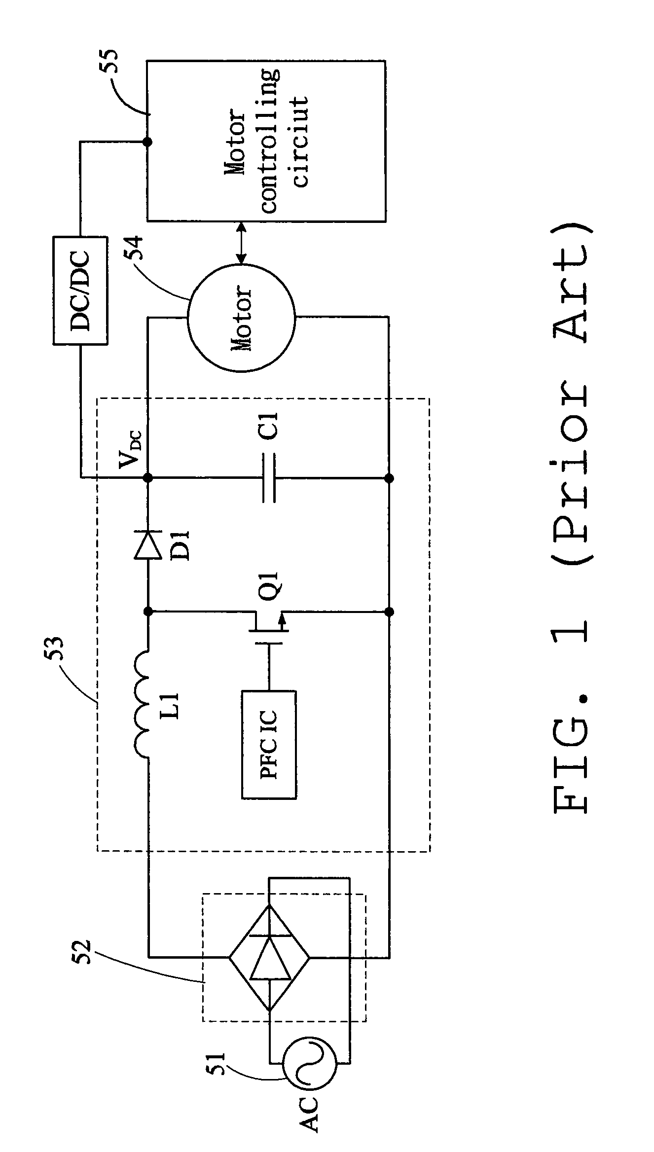
However, the direct current voltage VDC is a constant value, i.e., the voltage level of the direct current voltage VDC can not be regulated.

Method used


Image

  • Fan and motor control device
  • Fan and motor control device
  • Fan and motor control device

Examples


Embodiment Construction

[0017]The preferred embodiments of a fan and motor control device of the present invention will be apparent from the following detailed description, which proceeds with reference to the accompanying drawings.

[0018]The fan of the present invention includes an impeller, a motor and a motor control device. The motor is connected with the impeller for rotating the impeller. The motor control device is used for driving the motor to operate.

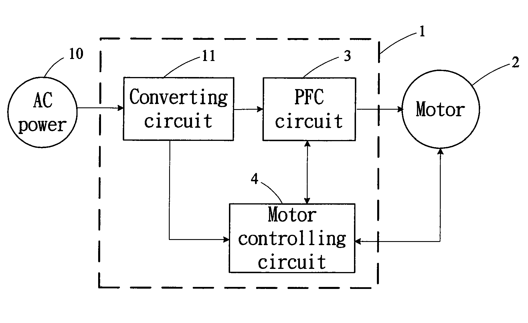
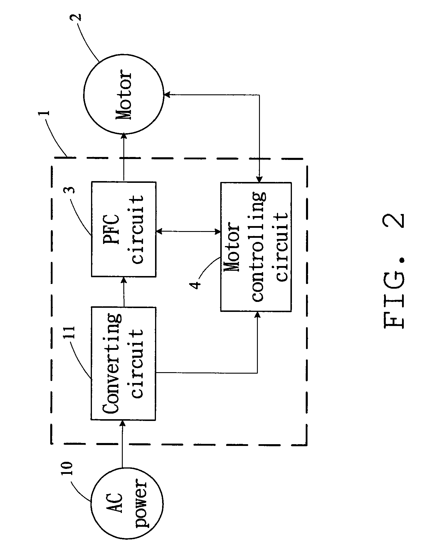
[0019]Please refer to FIG. 2 and FIG. 3, the motor control device 1 of the present invention is electrically connected with an alternating current power source 10 and the motor 2, respectively. The motor control device 1 includes a converting circuit 11, a power factor correction (PFC) circuit 3 and a motor controlling circuit 4. The converting circuit 11 is electrically connected with the alternating current power source 10. The power factor correction circuit 3 is electrically connected with the converting circuit 11, the motor 2 and the motor contro...


PUM


Abstract

A fan includes a motor control device which is electrically connected with a motor and an alternating current power source. The motor control device includes a converting circuit, a power factor correction circuit and a motor controlling circuit. The voltage of the alternating current power source is converted to be direct current voltage by the converting circuit and the power factor correction circuit, and then the direct current voltage is outputted to the motor control circuit. The motor controlling circuit generates a driving signal in accordance with the direct current voltage for driving the motor to operate.

Description

CROSS REFERENCE TO RELATED APPLICATIONS[0001]This Non-provisional application claims priority under 35 U.S.C. §119(a) on Patent Application No(s). 097146380, filed in Taiwan, Republic of China on Nov. 28, 2008, the entire contents of which are hereby incorporated by reference.BACKGROUND OF THE INVENTION[0002]1. Field of Invention[0003]The present invention relates to a fan and a motor control device, and in particular to a fan and a motor control device which drives a motor to operate via a voltage signal provided by a power factor correction circuit or via a pulse-width modulation signal and the voltage signal provided by the power factor correction circuit.[0004]2. Related Art[0005]Since the environmental protection regulations of every country have been rigid day by day, the trend of developing the driver of brushless DC motor is towards energy saving and superior quality of power source. Therefore, a power factor correction (PFC) circuit is normally disposed in the motor system ...

Claims


Application Information

Patent Timeline
Patent Type & Authority Applications(United States)
IPC IPC(8): H02P27/00
CPCH02P6/008H02P2201/15H02P7/29H02P6/26
Inventor TSENG, WEI-SHUOWEI, CHIA-PINKUO, CHIH-HSIANG
Owner DELTA ELECTRONICS INC
Learn More